Energy management system and control method therefor

Inactive Publication Date: 2018-01-04
KIM YOUNG BUM
View PDF2 Cites 11 Cited by
  • Summary
  • Abstract
  • Description
  • Claims
  • Application Information

AI Technical Summary

Benefits of technology

[0047]The present invention may reduce costs for constructing additional power

Problems solved by technology

As the convergence of electronic devices leads to a tendency of increasing Internet of Things (IoT) devices, energy consumption is expected to sharply grow.
Such a system exhibits a limitation in reducing energy consumption because energy management components of the system consume other power.
The system also suffers from the problem that it cannot cut off the power of existing electronic devices.
Although some devices come up with power measuring functionality, there are generally no proactive, energy saving schemes for allowing the user to save energy.
For example, the smart meter reports only the total power usage per household but does not how an individual piece of equipment consumes power, rendering energy management difficult or inefficient.
The power measuring AC receptacle, although letting it known how much power a device consumes, is of no proactive help to the user in light of energy savings.
However, the energy saving effect for home users is overwhelmed by the complexity in implementation, cost of equipment, and maintenance work.
A more serious situation is that additional energy consumption arises from devices that adopt the above-mentioned techniques introduce

Method used


Image

  • Energy management system and control method therefor
  • Energy management system and control method therefor
  • Energy management system and control method therefor

Examples


first embodiment

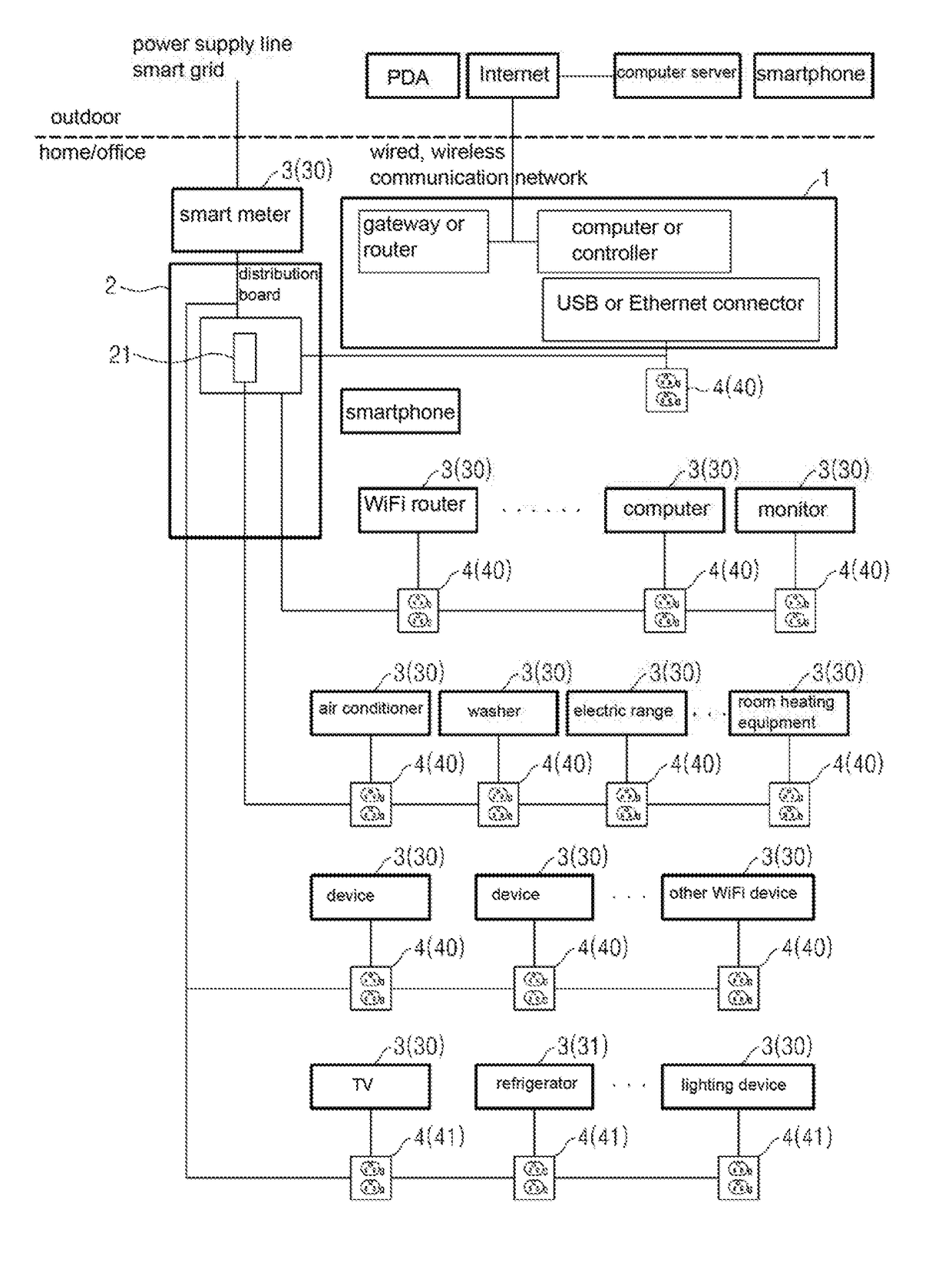
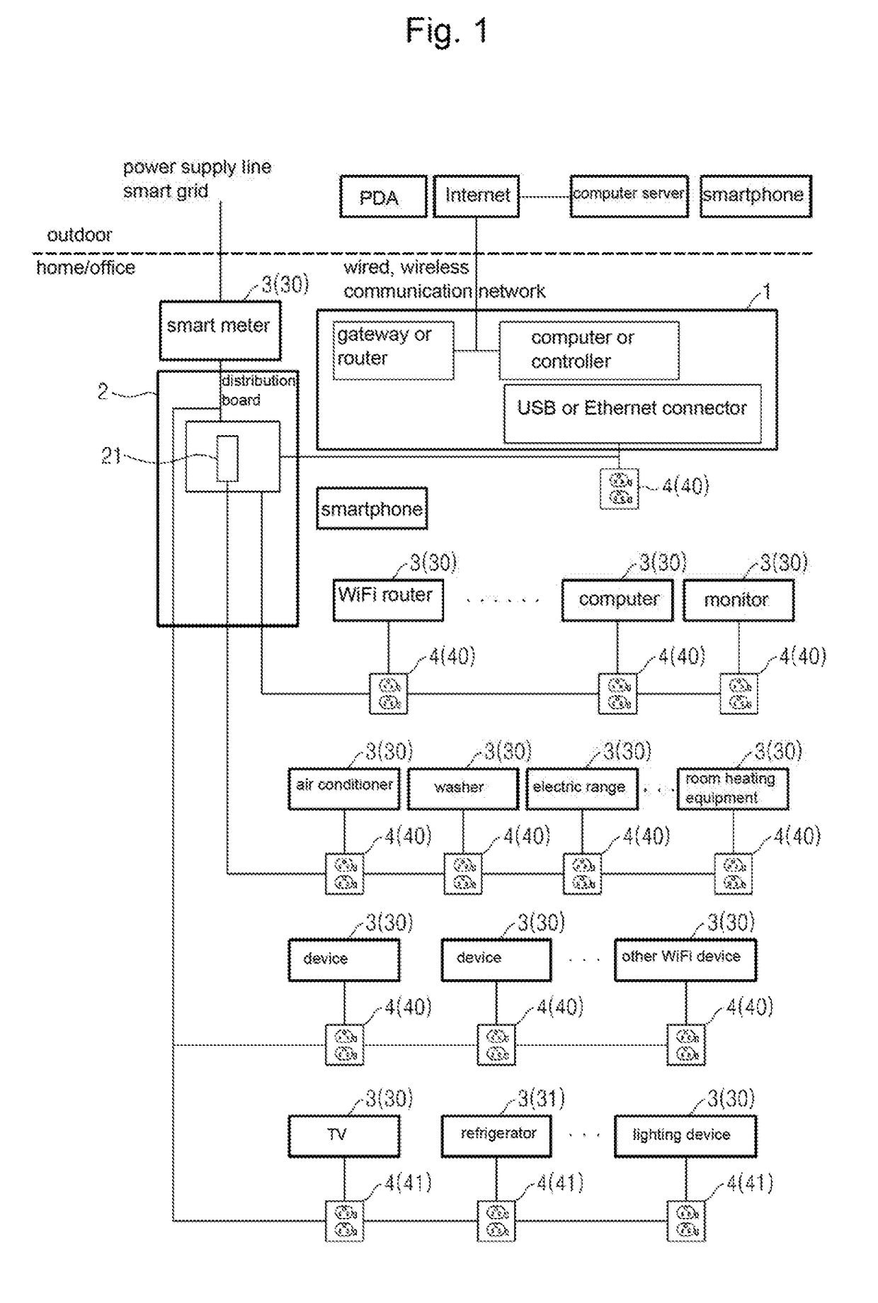
[0076]FIG. 1 is a block diagram illustrating a configuration of an energy management system according to the present invention. Referring to FIG. 1, the energy management system of the present invention is a wide area network for home or office, which includes a central management device 1 (applicable to, e.g., a smart meter, a wall pad, a separate dedicated device, a PC, a smart TV, or a smart refrigerator), at least one master device (at least one of reference numerals 3), and multiple slave devices (the remainder of the reference numerals 3 except for the master device(s))

[0077]The slave devices 3, as multiple home or office devices, such as a TV, a PC, a game console, an oven, a washer, a lamp, and a room cooler / heater, may be remotely controlled and may measure energy. The slave devices may wiredly or wirelessly communicate with the master device and may wiredly or wirelessly communicate with the outside, e.g., a portable device, such as a computer, a smart phone, or a tablet P...

second embodiment

[0131][Second embodiment] Meanwhile, the scheme in the configuration according to the first embodiment basically proposes that device IDs are basically set by the manufacturer upon manufacturing the devices to distinguish the devices from each other. The scheme, however, would take too long to be applicable to all the manufacturers and is thus expected to be difficult to put in widespread use.

[0132]The second embodiment of the present invention addresses such issue.

[0133]FIG. 10 is a block diagram illustrating a configuration of an energy management system according to a second embodiment of the present invention. Referring to FIG. 10, the energy management system of the present invention, similar to the configuration of FIG. 1, is a wide area network for home or office including a central management device 1-1 (the example of FIG. 10 represents the state of it having been applied to a smart meter), at least one master device (at least one of reference numerals 3), and multiple slav...

third embodiment

[0182][Third embodiment] Meanwhile, the configurations according to the first embodiment and the second embodiment of the present invention require separate wiring construction for existing receptacles, raising construction costs.

[0183]The third embodiment of the present invention addresses such issue.

[0184]FIG. 20 is a block diagram illustrating a configuration of an energy management system according to the third embodiment of the present invention. Referring to FIG. 20, the energy management system according to the third embodiment of the present invention, similar to the configuration of the second embodiment, includes a central management device 1-2, multiple devices 3, and receptacles 4.

[0185]At this time, according to the third embodiment of the present invention, some slave devices (e.g., at least some IoT devices) may have a manual / remote power supply / cutoff unit so that the power plug of the device can be inserted into an existing receptacle and the device can be supplied ...


PUM


Abstract

An energy management system of the present invention can measure and integrate a power consumption amount of each device, can integrate and monitor regional total power consumption amounts, and allows energy to be effectively used by collecting, analyzing, storing and transmitting a use pattern and data through the Internet of Things (IoT) between devices and completely and automatically cutting off and controlling the power to be wasted in a device when the device is not used. The energy management system remotely controls devices and allows energy to be effectively managed through the minimization of power consumption by automatically and completely cutting off the power to be supplied to the devices when the devices are not used, and by cutting off the power to be supplied to the system when the power of all the devices connected to the system is cut off and when the system is in standby.

Description

CROSS-REFERENCE TO RELATED APPLICATIONS[0001]This patent application is a national-stage application of PCT / KR2016 / 000243 filed on Jan. 11, 2016 which claims priority under 35 U.S.C. §119 to Korean Patent Application Nos. 10-2015-003210, 10-2015-0009076, and 10-2015-0028858, respectively filed on Jan. 9, 2015, Jan. 20, 2015, and Mar. 2, 2015, in the Korean Intellectual Property Office, the disclosures of which are incorporated by reference herein in their entireties.TECHNICAL FIELD[0002]The present invention relates to a smart home / building energy management system for efficient use of energy in, e.g., houses (smart homes), offices, buildings, and factories.DISCUSSION OF RELATED ART[0003]As the convergence of electronic devices leads to a tendency of increasing Internet of Things (IoT) devices, energy consumption is expected to sharply grow. Due to such expectation, the International Energy Agency (IEA) recommends the development of low-power electronic devices that consume less pow...

Claims


Application Information

Patent Timeline
IPC IPC(8): H02J13/00G05B19/042
CPCH02J13/0017G05B19/042G05B2219/2642G06Q50/06Y04S40/128G06Q10/06Y02B70/3225Y04S20/222Y04S20/242Y04S40/124Y02P90/82G05B15/02H02J2310/14H02J13/00016H02J13/00004H02J13/00028H02J3/14Y02B70/30Y02B90/20Y04S20/00H02J2310/66Y02B20/30G16Y10/35
Inventor KIM, YOUNG-BUMKIM, CHANG-HO
Owner KIM YOUNG BUM
Why Eureka
Try Eureka