Anti-rotation mount

Active Publication Date: 2018-01-04
TELEDYNE FLIR LLC
View PDF5 Cites 12 Cited by
  • Summary
  • Abstract
  • Description
  • Claims
  • Application Information

AI Technical Summary

Benefits of technology

The patent text describes an aircraft system that uses a camera and gimbal system to accurately point the camera as the aircraft changes position during flight. The gimbal system uses servomechanisms to stabilize the camera, but this can require sophisticated instrumentation and significant power consumption. The text also mentions a need for a mounting system to manage vibration and minimize the rotation of the camera caused by vibration. The technical effect of this patent is to provide a solution for stabilizing image quality during flight, while minimizing the need for expensive and power-hungry equipment.

Problems solved by technology

Aircraft vibration can degrade camera performance.
Images from the camera can be unsteady and / or blurred if the field of view of the camera is not stabilized during flight.
In particular, small, vibration-induced changes to the angular orientation of the camera, relative to the aircraft, can produce unacceptably large shifts in the field of view, especially if the camera is being used to view a distant target or scene.
However, such active compensation may need to be applied with great accuracy, high gain, and considerable speed, to effectively stabilize the image when aircraft vibration is transmitted to the camera.
As a result, active compensation can require sophisticated instrumentation and substantial power consumption and generally is effective only for low vibration frequencies.

Method used


Image

  • Anti-rotation mount
  • Anti-rotation mount
  • Anti-rotation mount

Examples


embodiments ii

B. Selected Embodiments II

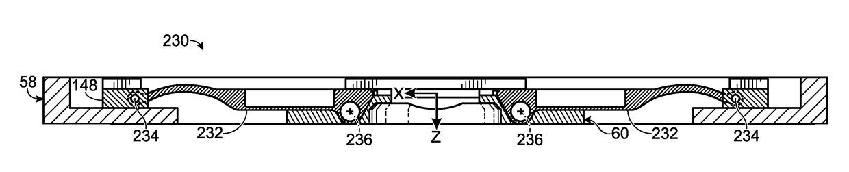
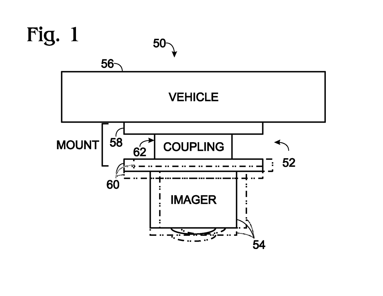
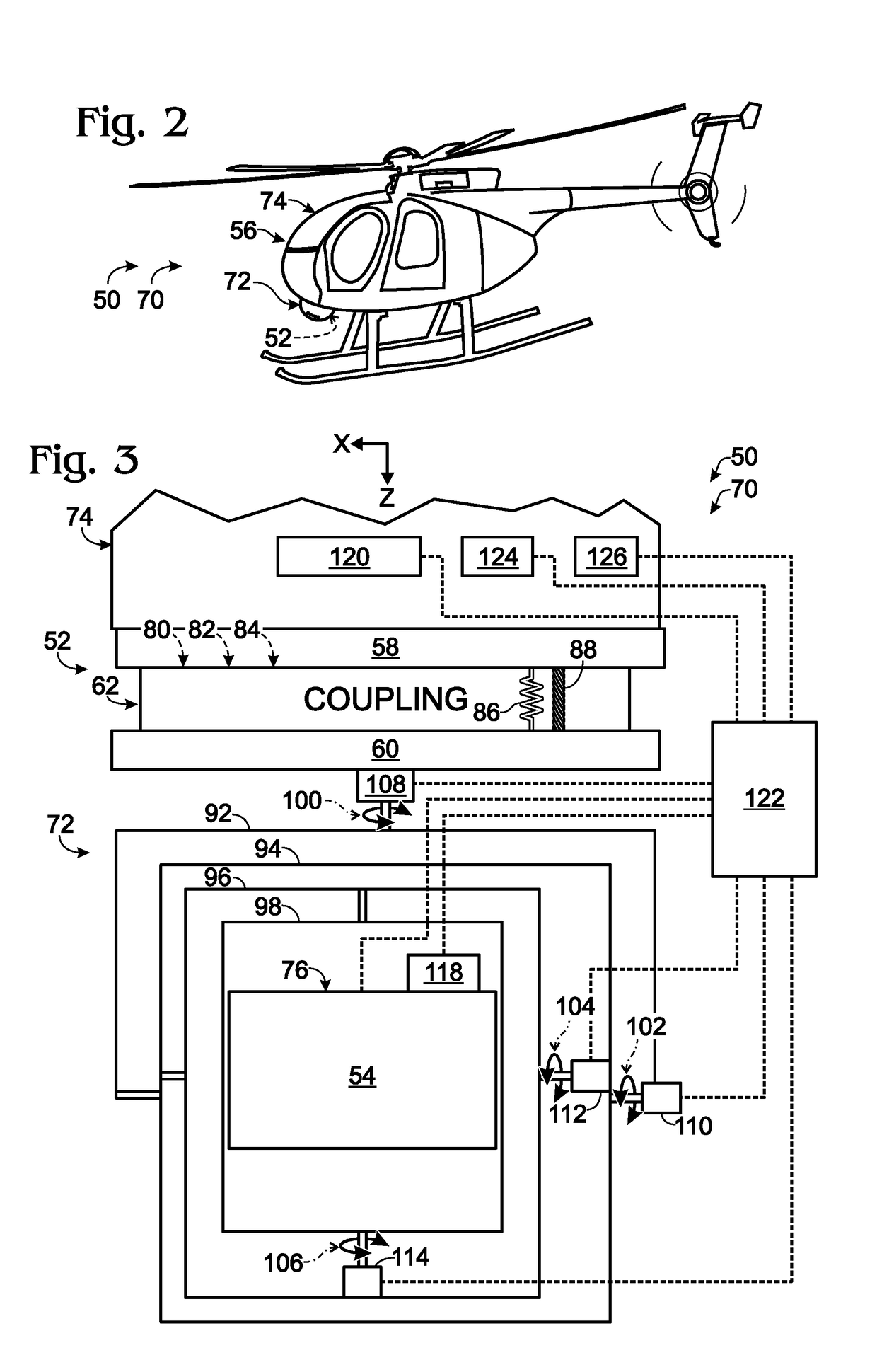
[0120]Paragraph 1. An imaging system, comprising: (A) a mount comprising (i) a first frame member having a fixed relation to a set of mutually transverse X, Y, and Z axes, (ii) a coupling assembly, (iii) a second frame member connected to the first frame member via the coupling assembly, such that the frame members are not permitted to rotate relative to one another, and (iv) X-axis, Y-axis, and Z-axis coupling structures each formed at least partially by the coupling assembly and permitting axial motion of the frame members relative to one another only substantially parallel to the X axis, Y axis, and Z axis, respectively; and (B) an image detector connected to the mount via the second frame member.

[0121]Paragraph 2. The imaging system of paragraph 1, wherein at least a portion of the X-axis coupling structure is nested in at least a portion of the Y-axis coupling structure.

[0122]Paragraph 3. The imaging system of paragraph 1 or 2, wherein one of the coupl...


PUM


Abstract

Imaging system comprising an anti-rotation mount and an image detector. The mount may comprise a first frame member having a fixed relation to a set of mutually transverse X, Y, and Z axes, and a second frame member. The second frame member may be connected to the first frame member via a coupling assembly, such that the frame members are not permitted to rotate relative to one another. The mount also may comprise X-axis, Y-axis, and Z-axis coupling structures each formed at least partially by the coupling assembly and each permitting axial motion of the frame members relative to one another only substantially parallel to the X axis, Y axis, and Z axis, respectively. The image detector may be connected to the mount via the second frame member.

Description

CROSS-REFERENCE TO RELATED APPLICATIONS[0001]This application is a continuation of International Patent Application No. PCT / EP2016 / 022705 filed Mar. 16, 2016 and entitled “ANTI-ROTATION MOUNT,” which is incorporated herein by reference in its entirety.[0002]International Patent Application No. PCT / EP2016 / 022705 filed Mar. 16, 2016 claims priority to and the benefit of U.S. Provisional Patent Application No. 62 / 133,773 filed Mar. 16, 2015 and entitled “ANTI-ROTATION MOUNT,” which is hereby incorporated by reference in its entirety.CROSS-REFERENCES TO OTHER MATERIALS[0003]Each of the following patent documents is incorporated herein by reference in its entirety for all purposes: U.S. Pat. No. 8,385,065 B2, issued Feb. 26, 2013; and PCT Patent Application Publication No. WO 2012 / 170673 A1, published Dec. 13, 2012.INTRODUCTION[0004]An aircraft may be equipped with a gimbal system including a camera. The gimbal system enables the camera to be accurately pointed as the attitude and locati...

Claims


Application Information

Patent Timeline
IPC IPC(8): H04N5/232B64D47/08H04N5/225
CPCH04N5/2328B64D47/08H04N5/2252H04N5/2253G03B15/006G03B17/561H04N23/685B64U20/87H04N23/51H04N23/54
Inventor ZEISE, STEPHEN W.HAMRI, NAJATWEAVER, JAMES H.VAN EEDEN, TYLDENANDERSON, ROBERT D.
Owner TELEDYNE FLIR LLC
Why Eureka
Try Eureka