Three-dimensional modeling device

a three-dimensional modeling and device technology, applied in the field of three-dimensional modeling devices, can solve the problems of reducing the modeling accuracy of three-dimensional shaped objects in some cases, complicated mechanisms for changing the capacity of the chamber and discharging fumes from the chamber

Inactive Publication Date: 2018-01-11
SEIKO EPSON CORP
View PDF5 Cites 4 Cited by
  • Summary
  • Abstract
  • Description
  • Claims
  • Application Information

AI Technical Summary

Benefits of technology

[0005](1) According to an aspect of the invention, a three-dimensional modeling device is provided. The three-dimensional modeling device includes a modeling section supplied with a material including a metal powder, a laser source adapted to emit a laser used to sinter or melt the metal powder, and an optical component through which the laser emitted from the laser source passes in the midway to the material on the modeling section, wherein the optical component is provided with a first area, which faces to the modeling section, and through which the laser passes, and a second area higher in surface free energy than the first area is disposed in at least a part of a periphery of the first area. According to the three-dimensional modeling device having such a configuration, since the fumes become more apt to adhere to a peripheral area (the second area) of an area (the first area), through which the laser passes, of the optical component than to the first area, it is possible to prevent that the modeling accuracy of the shaped article is degraded due to the adhesion of the fumes to the optical component with a simple configuration.
[0006](2) In the three-dimensional modeling device according to the aspect of the invention, the first area may be provided with liquid repellency. According to such a configuration, the surface free energy of the first area can easily be reduced.
[0007](3) In the three-dimensional modeling device according to the aspect of the invention, the second area may be provided with lyophilicity. According to such a configuration, the surface free energy of the second area can easily be increased.
[0008](4) In the three-dimensional modeling device according to the aspect of the invention, the first area may be provided with a moth-eye structure. According to such a configuration, adhesion of the fumes to the first area can more efficiently be prevented.
[0009](5) In the three-dimensional modeling device according to the aspect of the invention, the three-dimensional modeling device may further include a removing section adapted to remove a particle adhering to the first area. According to such a configuration, adhesion of the fumes to the first area can more efficiently be prevented.

Problems solved by technology

If the fumes adhere to an optical component through which the laser passes, the degree of convergence of the laser to the metal powder is deteriorated to thereby degrade the modeling accuracy of the three-dimensional shaped article in some cases.
However, in the technology of Document 1, there is a possibility that the mechanism for changing the capacity of the chamber and the mechanism for discharging the fumes from the chamber become complicated.

Method used


Image

  • Three-dimensional modeling device
  • Three-dimensional modeling device
  • Three-dimensional modeling device

Examples


first embodiment

A. First Embodiment

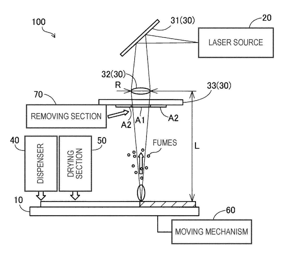
[0015]FIG. 1 is an explanatory diagram showing a schematic configuration of a three-dimensional modeling device 100 according to a first embodiment of the invention. The three-dimensional modeling device 100 is provided with a modeling section 10, a laser source 20, and optical components 30. Further, the three-dimensional modeling device 100 according to the present embodiment is provided with a dispenser 40, a drying section 50, a moving mechanism 60, and a removing section 70.

[0016]The modeling section 10 is a modeling stage supplied with a material including a metal powder. The upper surface of the modeling section 10 is flat, and the material is supplied on the flat upper surface. The modeling section 10 can be displaced by the moving mechanism 60 in horizontal directions and a vertical direction.

[0017]The dispenser 40 is a device for supplying the material on the modeling section 10. In the present embodiment, the dispenser 40 supplies the paste-like materia...

second embodiment

B. Second Embodiment

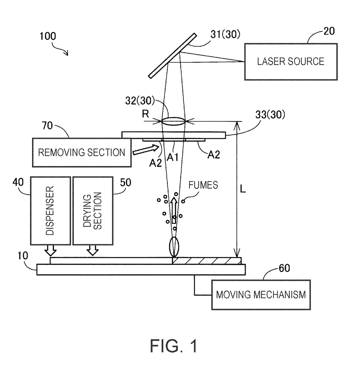
[0030]FIG. 2 is an explanatory diagram showing a schematic configuration of a three-dimensional modeling device 101 according to a second embodiment of the invention. The first embodiment described above and the second embodiment are different in the configuration of the optical components 30, and other points are common to the first embodiment and the second embodiment. Therefore, the description of the constituents other than the optical components 30 will hereinafter be omitted.

[0031]In the second embodiment, the optical components 30 include the mirror 31 and the lens 32, but do not include the window. In the present embodiment, the lens 32 is fitted in a through hole provided in a central part of a lens holder 80. The lens holder 80 is formed of a material such as resin or metal different from the material (glass) of the lens 32.

[0032]In the present embodiment, the lens 32 among the optical components 30 is provided with the first area A1, through which the ...

third embodiment

C. Third Embodiment

[0034]FIG. 3 is an explanatory diagram showing a schematic configuration of a three-dimensional modeling device 103 according to a third embodiment of the invention. The first embodiment described above and the third embodiment are different in the configuration of the optical components 30, and other points are common to the first embodiment and the third embodiment. Therefore, the description of the constituents other than the optical components 30 will hereinafter be omitted.

[0035]In the third embodiment, the optical components 30 include the mirror 31 and the lens 32, but do not include the window. In the present embodiment, the lens 32 is disposed between the laser source 20 and the mirror 31.

[0036]In the present embodiment, the mirror 31 among the optical components 30 is provided with the first area A1, through which the laser passes, on the surface facing to the modeling section 10. Further, on the periphery of the first area A1 of the mirror 31, there is ...


PUM

PropertyMeasurementUnit
surface free energyaaaaaaaaaa

Abstract

A three-dimensional modeling device includes a modeling section supplied with a material including a metal powder, a laser source adapted to emit a laser used to sinter or melt the metal powder, and an optical component through which the laser emitted from the laser source passes in the midway to the material on the modeling section. The optical component is provided with a first area, which faces to the modeling section, and through which the laser passes, and a second area higher in surface free energy than the first area is disposed in at least a part of a periphery of the first area.

Description

BACKGROUND1. Technical Field[0001]The present invention relates to a three-dimensional modeling device.2. Related Art[0002]In the past, there has been known a three-dimensional modeling device which irradiates metal powder with a laser to sinter, or melt and then solidify the metal powder to thereby manufacture a three-dimensional shaped article. In such a three-dimensional modeling device, when the metal powder is sintered or melted, fumes are generated in some cases. The fumes denote fine particles generated by aggregating the metal vapor. If the fumes adhere to an optical component through which the laser passes, the degree of convergence of the laser to the metal powder is deteriorated to thereby degrade the modeling accuracy of the three-dimensional shaped article in some cases. Regarding such a problem, for example, in JP-A-2010-265521 (Document 1), there is disclosed the following technology. That is, in the three-dimensional modeling device, which manufactures a three-dimens...

Claims


Application Information

Patent Timeline
Patent Type & Authority Applications(United States)
IPC IPC(8): B23K26/16B22F3/105B23K26/064B23K26/342
CPCB23K26/16B22F3/1055B22F2003/1056B33Y30/00B23K26/064B23K26/342B22F2998/10B33Y10/00Y02P10/25B22F12/10B22F12/41B22F12/70B22F12/44B22F10/16B22F1/107B22F3/004B22F1/142B22F10/20
Inventor MIYASHITA, TAKESHI
Owner SEIKO EPSON CORP
Why Eureka
Try Eureka