Spatially adaptive tone mapping operator

a tone mapping and spatial adaptation technology, applied in image enhancement, image analysis, instruments, etc., can solve the problems of loss of detail, tmo works reasonably well, and no ideal solution exists for processing the output of wdr digital cameras, so as to reduce the global contrast of hdr images, increase contrast, and boost image contrast

Active Publication Date: 2018-01-11
MICRO BIZ VENTURES
View PDF0 Cites 9 Cited by
  • Summary
  • Abstract
  • Description
  • Claims
  • Application Information

AI Technical Summary

Benefits of technology

[0009]According to an exemplary embodiment, a tone mapping operator (TMO) function combines the use of locally determined illuminations (or approximations to the local illumination) and locally determined variances (or equivalently local standard deviations). The illumination and variance are then used to increase contrast locally and to decrease the global contrast of HDR images. The TMCEO described herein provides a concrete e...

Problems solved by technology

The basic Retinex method produces some artifacts; most notably, haloes appear around very bright or dark localized regions.
In spite of the progress in TMOs, no ideal solution exists for processing the output of WDR digital cameras.
The global ...

Method used


Image

  • Spatially adaptive tone mapping operator
  • Spatially adaptive tone mapping operator
  • Spatially adaptive tone mapping operator

Examples


example 1

TMCEO Processing of Architectural Image

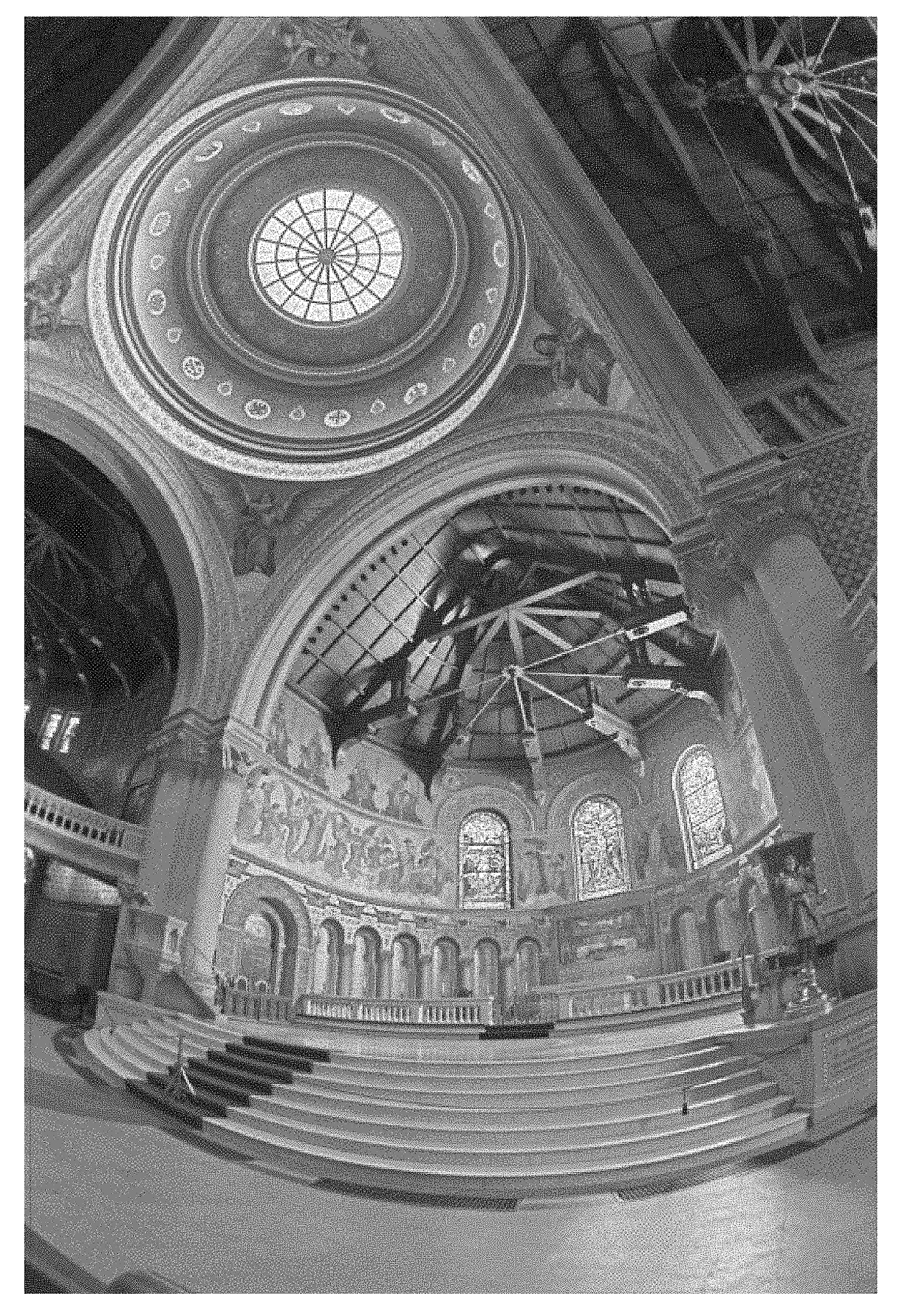
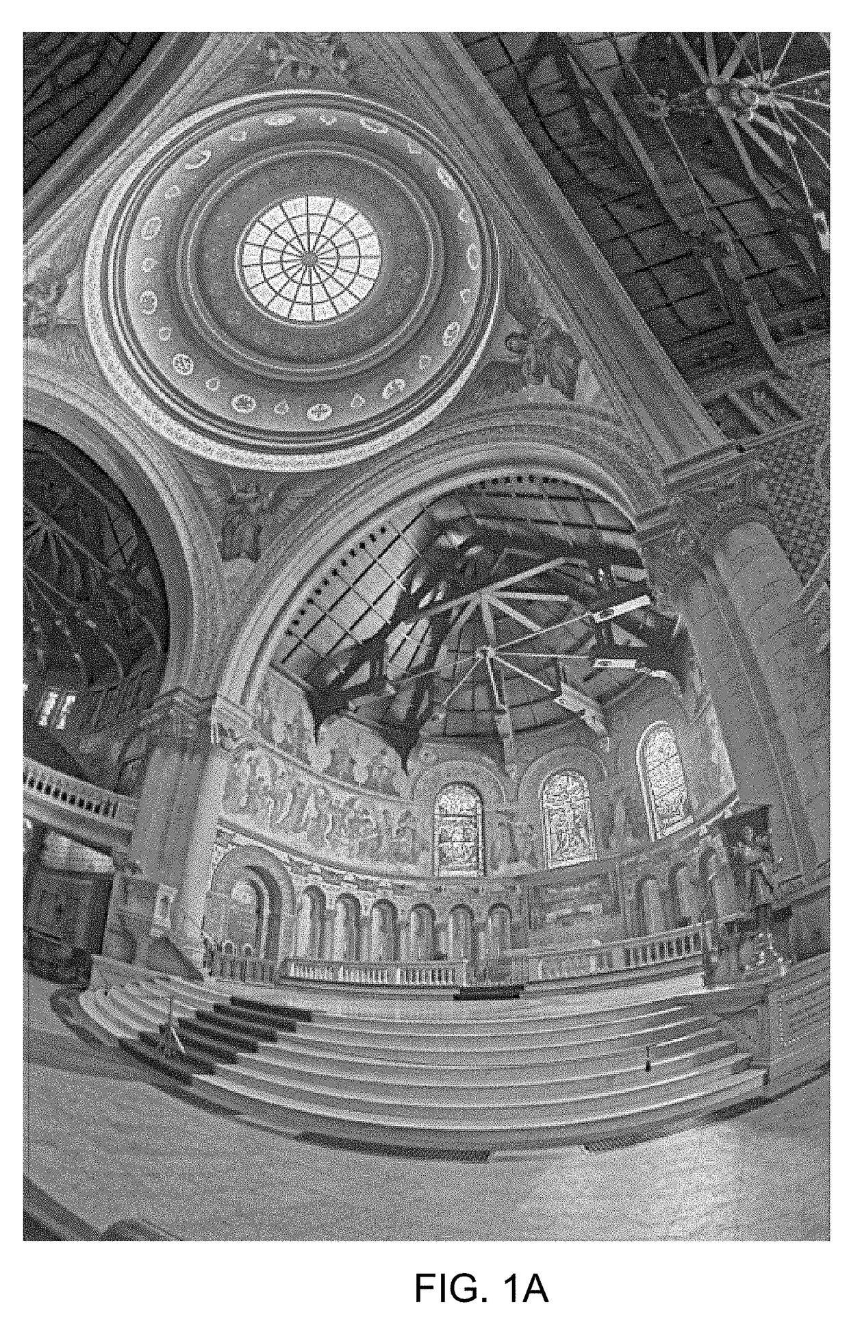
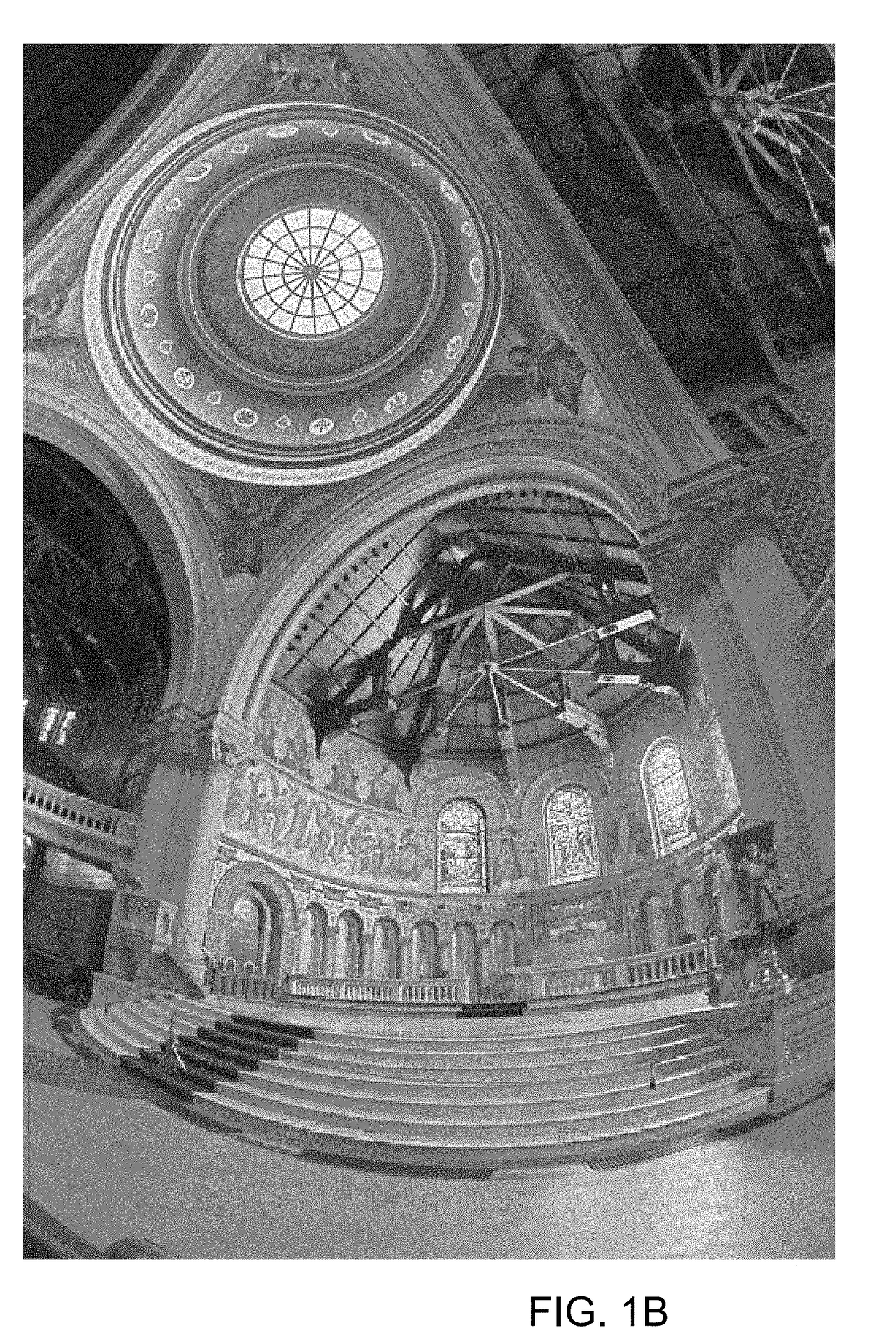
[0033]The performance of the inventive TMCEO approach can be judged by applying the sample algorithm of Equations (9) and (10) to several HDR images. A common set of test images used to test TMOs is the Debevec Library [6] of HDR images. The test images were all processed with two sets of values for the parameters that control the sample TMCEO of Equations (9) and (10): set A with α=0.36, α=0.03, β=1.0, γ=0.03 (FIG. 1A), and set B with α=0.36, α=0.0, β=1.0, γ=0.0 (FIG. 1B). The parameters of set A are used to enhance the contrast in regions with low illumination levels. In set A, non-zero values of a and y are both needed because a times the ratio of the residual to the local standard deviation is a term in the equation for the reduced dynamic range luminance (Equation 10). The ratio of the residual to the local standard deviation can be positive or negative, so there must be a positive shift to a base level above zero as provided by a positive...

example 2

TMCEO Processing of Landscape Image

[0035]FIGS. 2A-2C show the Vine Sunset HDR image from the Debevec Library processed using this TMO with parameter sets A and B and processed with just clipping above a fixed high luminance value, respectively.

[0036]The Vine Sunset HDR image from the Debevec Library is a high key image (dominated by bright regions). The Reinhard et al. TMO produces little visibility of details in the dark regions of high key images in general. By using the TMCEO described here, with the contrast enhancement turned on, the details in the low light regions of the image are more apparent, as can be seen in FIG. 2A. The contrast enhancement produces some pixels that are mapped to black in FIG. 2A. Such artifacts depend on the noise level in the image—there is a fair amount of noise in the sky region of this image and this noise, contrast enhanced, produces the dark pixels. From a surveillance perspective, FIG. 2A is preferred over the bottom two panels because the dark ...

example 3

TMCEO Processing of Architectural Image

[0037]FIGS. 3A and 3B provide a comparison of image processing using the method described by Ward Larson, G., Rushmeier, H., and Piatko, C. (“A Visibility Matching Tone Reproduction Operator for High Dynamic Range Scenes,” in IEEE Transactions on Visualization and Computer Graphics 3, 4, 1997, pp. 291-306), shown in FIG. 3A and the same image processed using the TMCEO method (FIG. 3B). The image is from Fattal, R., Lischinski, D., and Werman, M. (“Gradient Domain High Dynamic Range Compression,” in Proc. SIGGRAPH Annu. Conf. Computer Graphics, 2002, pp. 249-256.)


PUM


Abstract

A method for spatially-adaptive tone mapping in an image having high dynamic range includes using a computing device to receive an input image from an image sensor comprising a plurality of pixels having pixel locations and determine within the input image a plurality of local size scales, each comprising a neighborhood having substantially constant illumination. The variation in reflectance within each neighborhood is estimated and local contrast within each neighborhood is enhanced. Using the illumination and variation within the contrast-enhanced neighborhoods, the image is remapped to a reduced dynamic range to generate an output image.

Description

RELATED APPLICATIONS[0001]This application claims the benefit of the priority of U.S. Provisional Application No. 62 / 360,888, filed Jul. 11, 2016, which is incorporated herein by reference in its entirety.FIELD OF THE INVENTION[0002]The present invention relates to method and system for a spatially-adaptive tone mapping, and more particularly to a tone mapping operator that reduces illumination dynamic range and enhances local reflective contrastBACKGROUND OF THE INVENTION[0003]High dynamic range (HDR) scenes often occur in natural settings. Outdoor scenes that include direct sunlight and deep shadows inherently have a large dynamic range. HDR scenes also often occur in surveillance settings, e.g., scenes that include both indoor and outdoor illumination. Common display devices, LCD flat panel displays, CRTs, and color prints, and the human eye have a limited dynamic range: roughly 100:1. In computer graphics, the dynamic range of scene is expressed as the ratio of the highest scene...

Claims


Application Information

Patent Timeline
IPC IPC(8): G06T5/00
CPCG06T5/002G06T2207/10016G06T2207/10024G06T5/007G06T5/008G06T2207/20208
Inventor PUETTER, RICHARD C.JUNKKARINEN, VESA
Owner MICRO BIZ VENTURES
Why Eureka
Try Eureka