Device And Method For Energy Harvesting Using A Self-Oscillating Power-On-Reset Start-Up Circuit With Auto-Disabling Function

Inactive Publication Date: 2018-01-18
NANYANG TECH UNIV +1
View PDF4 Cites 12 Cited by
  • Summary
  • Abstract
  • Description
  • Claims
  • Application Information

AI Technical Summary

Benefits of technology

This patent describes a device and method for energy harvesting. The device has a starting circuit that boosts the input voltage from an energy source during the startup phase, a main boost circuit that increases the voltage during the steady state phase, and a clock generator circuit that controls voltage boosting using clock signals. The device has a switching circuit that powers the clock generator circuit using either the starting circuit or the main boost circuit at any given time. The method involves generating pulses to control the starting of the device, generating clock signals from the pulses, boosting the input voltage using an auxiliary boost circuit, and powering the clock generator in response to the boosted voltage and the clock signals. The technical effect of this device and method is increased energy harvesting efficiency, especially in devices that require a reliable and stable power source.

Problems solved by technology

However, due to constraints on thermoelectric generator (TEG) physical dimensions and a limited temperature difference between the human body and the environment, a TEG usually exhibits sub-mW output power and low output voltage (e.g., ranging from a few hundred millivolts) which cannot be directly utilized to power electronic circuits.
Therefore, major design challenges in a thermoelectric energy harvester system include designing a low voltage self-start-up circuit and a high efficiency boost converter for a low voltage power source.
However these approaches require external motion force to trigger start up, large system size, or increased fabrication cost or may lack a shut-down mechanism for an electrical start-up circuit leading to leakage current causing significant efficiency degradation during a normal operation mode.

Method used


Image

  • Device And Method For Energy Harvesting Using A Self-Oscillating Power-On-Reset Start-Up Circuit With Auto-Disabling Function
  • Device And Method For Energy Harvesting Using A Self-Oscillating Power-On-Reset Start-Up Circuit With Auto-Disabling Function
  • Device And Method For Energy Harvesting Using A Self-Oscillating Power-On-Reset Start-Up Circuit With Auto-Disabling Function

Examples


Embodiment Construction

[0019]The following detailed description is merely exemplary in nature and is not intended to limit the embodiments or the application and uses of the embodiments. Furthermore, there is no intention to be bound by any theory presented in the preceding background of the embodiments or the following detailed description. It is the intent of this embodiment to present a device and method for energy harvesting using a self-oscillating power-on reset start-up circuit with an auto-disabling function.

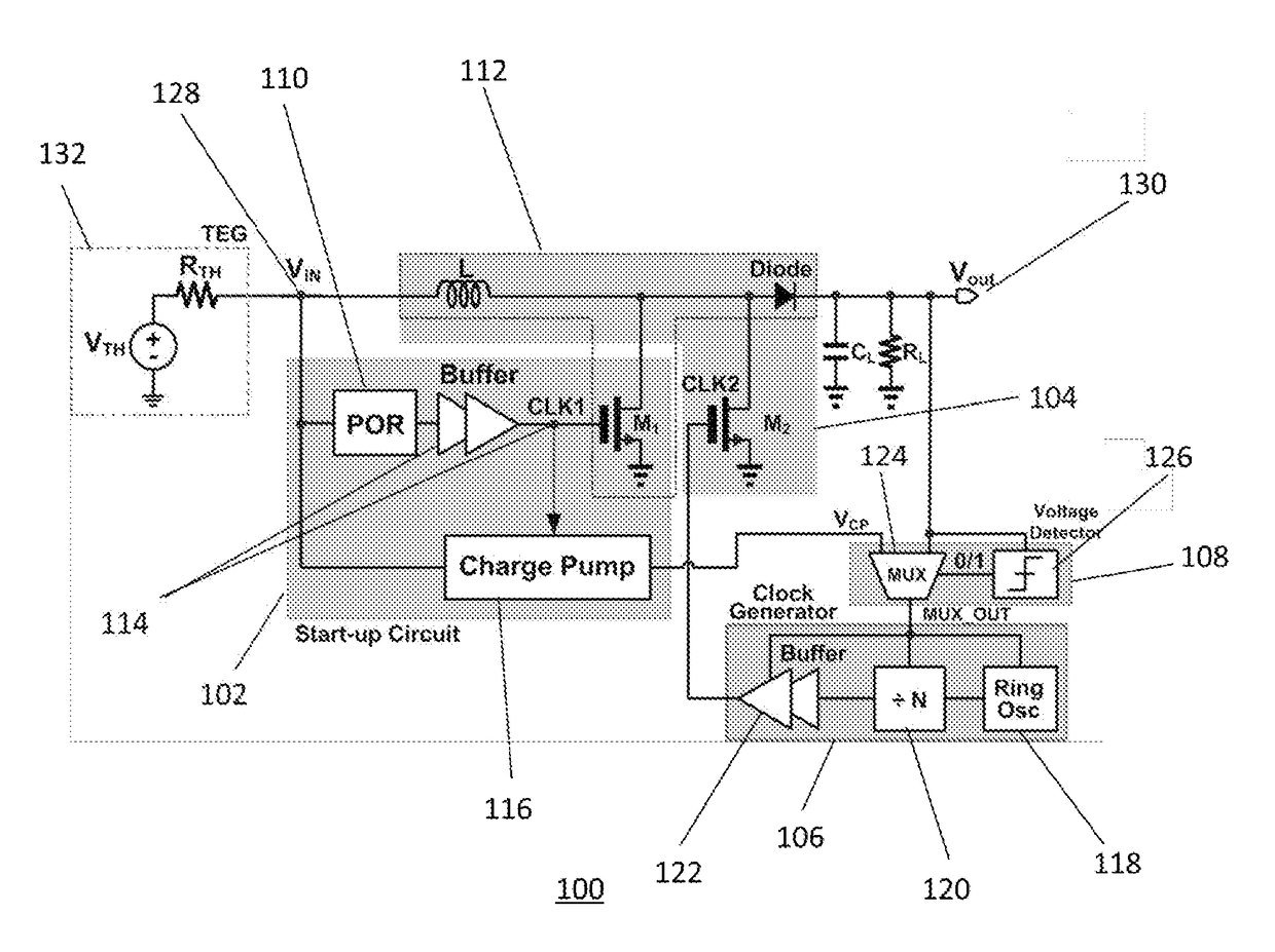
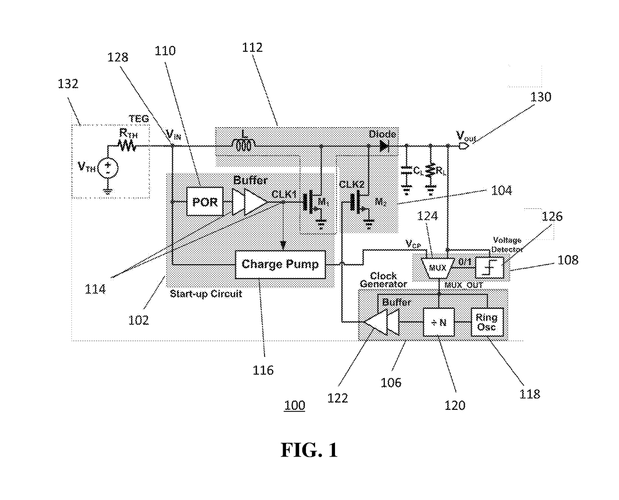
[0020]Referring to FIG. 1, a schematic of circuitry 100 depicts an overall circuit configuration of the device for energy harvesting in accordance to a present embodiment. As seen in FIG. 1, the device for energy harvesting can comprise a start-up circuit 102, a main boost circuit 104, a clock generator 106 and a switching circuit 108. In particular, the start-up circuit 102 can comprise a Power-On Reset (POR) circuit 110, an auxiliary boost circuit 112, an inverter chain buffer 114 and a char...


PUM


Abstract

Device and method for energy harvesting using a self-oscillating power-on reset start-up circuit. The device for energy harvesting comprises a start-up circuit for generating self-oscillation and initial boosting of an input voltage from an energy source during a start-up phase; a main boost circuit for boosting the input voltage during a steady state phase; a clock generator circuit for generating clock signals which control voltage boosting of the main boost circuit during the steady state phase; and a switching circuit coupled to the start-up circuit, the main boost circuit and the clock generator circuit for switching powering of the clock generator circuit between the start-up circuit and the main boost circuit such that the clock generator circuit is powered by only one of the start-up circuit and the main boost circuit at any point in time.

Description

PRIORITY CLAIM[0001]This application claims priority from Singapore Patent Application No. 10201500477Y filed on Jan. 21, 2015.FIELD OF INVENTION[0002]This embodiment broadly relates to an energy harvesting device and an energy harvesting method and in particular, relates to an energy harvesting device and an energy harvesting method using a self-oscillating power-on reset start-up circuit with automatic disabling function.BACKGROUND TO THE INVENTION[0003]Batteryless sensors, which harvest ambient energy as alternative power sources for long-term self-supplied operation, can have promising potentials for biomedical and wearable applications. Among various energy sources, thermal heat can provide an important energy source for implantable and wearable sensors because thermal heat can be easily accessible from the human body. However, due to constraints on thermoelectric generator (TEG) physical dimensions and a limited temperature difference between the human body and the environment...

Claims


Application Information

Patent Timeline
IPC IPC(8): H02M1/36H02M3/07H03K17/22H03K3/03
CPCH02M1/36H03K17/223H02M3/073H03K3/0315G05F3/08G06F1/04H03K19/0016H03K19/017581G06F1/26H02J7/345H02M3/156H02J50/001
Inventor GAO, YUANDAS, ABHIKKIM, TAE-HYOUNG
Owner NANYANG TECH UNIV
Why Eureka
Try Eureka