Tracking cardiac forces and arterial blood pressure using accelerometers

Active Publication Date: 2018-01-25
SHUSTERMAN VLADIMIR
View PDF0 Cites 55 Cited by
  • Summary
  • Abstract
  • Description
  • Claims
  • Application Information

AI Technical Summary

Benefits of technology

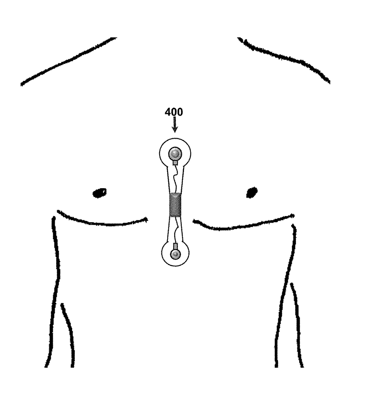
[0029]Placing the sensor for measuring blood pressure or blood-pressure wave (which is also referred to as the pulse wave or pulse pressure) on the torso eliminates vascular-activity confounders (which are present in the peripheral arteries) and simplifies the detection, separation, and tracking of non-local (systemic) patterns of cardiac forces and/or blood-pressure dynamics, which are primarily associated with changes in cardiac output, heart rate, and systemic vascular activity. In addition, placing the sensor in the vicinity of the central blood vessels also facilitates the detection of changes in those blood vessels. For example, placing the sensor in the vicinity of the abdominal aorta will facilitate the detection of an aortic a

Problems solved by technology

The detection, diagnosis, and monitoring of such abnormalities in mild, early-stage cases are challenging.
However, determining the patients who can benefit from cardiac resynchronization therapy, finding the optimal sites for placing the pacing electrodes, and determining the optimal timing for the pacing stimuli remain challenging.
However, BCG has been limited to a “lumped,” single-waveform representation of cardiac forces using a single sensor positioned at a single site.
Furthermore, the prior-art BCG devices were non-portable (e.g., a bed, platform, weighting scale).
Timely diagnosis and control of high arterial blood pressure are crucial for preventing life-threatening complications and end-organ damage but have been hamper

Method used


Image

  • Tracking cardiac forces and arterial blood pressure using accelerometers
  • Tracking cardiac forces and arterial blood pressure using accelerometers
  • Tracking cardiac forces and arterial blood pressure using accelerometers

Examples


Embodiment Construction

[0187]This disclosure contains some representative embodiments, which are provided primarily for illustrative purposes and which are not intended to limit the broad aspects of the invention. To that extent, elements and limitations that are disclosed, for example, in the Abstract, Summary, and Description of the Preferred Embodiments, but not explicitly set forth in the claims, should not be incorporated into the claims, singly or collectively, by implication, inference, or otherwise.

[0188]Any and all combinations of the features, functions, and concepts discussed in detail herein are contemplated as being part of the inventive subject matter (provided such concepts are not mutually inconsistent). For example, although differing in appearance, the individual systems and devices and functional componentry depicted and disclosed herein can each take on any of the various forms, optional configurations, and functional alternatives described above and below with respect to the other dis...


PUM


Abstract

Modular, miniaturized cardiovascular sensors, systems, methods, and wearable devices for the non-obtrusive evaluation, monitoring, and high-fidelity mapping of cardiac mechanical and electromechanical forces and central arterial blood pressure are presented herein. The sensor manufacturing process is also presented. Using accelerometers, the sensors register body-surface (preferably torso-surface) movements and vibrations generated by cardiac forces. The sensors may contain single-use or reusable components, which may be exchanged to fit different body sizes, shapes, and anatomical locations; they may be incorporated into clothing, bands, straps, and other wearable arrangements. The invention presents a practical, noninvasive solution for electromechanical mapping of the heart, which is useful for a wide range of healthcare applications, including the remote monitoring of heart failure status and the guidance of cardiac resynchronization therapy. Exercise and cardiovascular fitness tracking applications are also presented.

Description

CROSS-REFERENCE TO RELATED APPLICATIONS[0001]This application is a continuation-in-part of pending U.S. patent application Ser. No. 14 / 196,738, filed Mar. 4, 2014, which is a continuation-in-part of application Ser. No. 13 / 017,043, filed Jan. 30, 2011 (now U.S. Pat. No. 8,706,464), which are incorporated herein by reference. This application also claims the benefit of U.S. Provisional Application No. 62,442,371, filed Jan. 4, 2017, which is incorporated herein by reference.STATEMENT REGARDING FEDERALLY SPONSORED RESEARCH OR DEVELOPMENT[0002]This invention was made with government support under the grant R43HL114277 awarded by the National Institutes of Health. The government has certain rights in the invention.FIELD OF THE INVENTION[0003]This invention relates to the field of biomedical sensors and sensor manufacturing processes, methods, and systems for testing and monitoring cardiovascular activity, in particular: (i) integrated sensors, circuits, and systems for physiological sen...

Claims


Application Information

Patent Timeline
IPC IPC(8): A61B5/0205A61B5/08A61N1/362A61B5/00
CPCA61B5/02055A61B5/4818A61B5/6805A61B5/0826A61B5/4884A61B5/4848A61B5/7275A61N1/3627A61B5/021A61B5/029A61B2562/0219A61B5/0402A61B5/0488A61B5/0533A61B5/024A61B2560/0443A61B5/1102A61B2562/164A61B8/04A61B5/02007A61B5/02014A61B5/02116A61B5/02125A61B8/4236A61B5/6833A61B5/352A61B5/318A61B5/389
Inventor SHUSTERMAN, VLADIMIR
Owner SHUSTERMAN VLADIMIR
Why Eureka
Try Eureka