An active optical fibre

a technology of active optical fibers and optical fibers, applied in the field of active optical fibres, can solve the problems of poor thermal conductivity, limited pump power that can be coupled into such a double-clad optical fibre without providing suitable cooling systems, and generally degraded polymer materials, etc., to achieve the effect of increasing the thermal conductivity of the coating, increasing the operating temperature, and maximising the distan

Active Publication Date: 2018-01-25
COMMONWEALTH OF AUSTRALIA REPRESENTED BY DEPT OF DEFENCE DEFENCE SCI & TECH ORG
View PDF5 Cites 8 Cited by
  • Summary
  • Abstract
  • Description
  • Claims
  • Application Information

AI Technical Summary

Benefits of technology

[0030]In one embodiment of the laser system, the active optical fibre and the pump laser or pump laser array are remotely coupled via a passive optical fibre, and the active optical fibre includes a laser output aperture at a distal end of the active optical fibre. In this embodiment, the thermally conductive metal, graphite or other material of the coating supports a minimised distance between a proximal end of the active optical fibre coupled to the passive optical fibre and the laser output aperture. Also, the thermally conductive metal, graphite or other material of the coating supports a maximised distance between the active optical fibre and the pump laser or pump laser via the passive optical fibre. That is, the active optical fibre and the pump laser or pump laser array are remotely coupled and the increased operating temperature as well as increased thermal conductivity of the coating both allow the active optical fibre to be placed at a location remote to the pump laser or pump laser array and at a location close to the laser output aperture. Such a situation has the benefit of allowing the active fibre to be placed within space constrained environment whilst also minimising the distance the signal laser light must propagate within a waveguide of the laser system. Typically, the waveguide is a passive optical fibre but can also be an active optical fibre. In an example, the distance between the pump laser or pump laser array and the active optical fibre is between 1-10 metres. In another example, the distance is between 10-100 metres. In yet another example, the distance is between 100-10,000 metres. It will be appreciated by those persons skilled in the art that any separating distance between the active optical fibre and the pump laser or pump laser array can be employed by the system such that the separating distance is sufficient to thermally isolate the pump laser or pump laser array and the active optical fibre.
[0031]As described, the use of a high operating temperature thermally conductive coating (e.g. Aluminium, which can be up to 400° C.) enables a minimised cooling of the active optical fibre thus allowing the weight and size of the laser system to be distributed Also, the use of a high operating temperature thermally conductive coating preferentially allows the weight and size of the laser system to be concentrated at the pump laser or pump laser array thus minimising the weight and size of the active optical fibre situated near the laser output aperture. A secondary advantage to this laser system is, in one embodiment, the minimised propagation of laser light in the passive optical fibre situated after the active optical fibre, and thus the system serves to minimise impact of detrimental non-linear effects caused by propagation within this passive optical fibre.
[0032]In one embodiment, the thermally conductive metal, graphite or other material of the coating supports a minimised size, weight and cooling of the active optical fibre. Also, it will be appreciated that the pump laser or pump laser array and the active optical fibre can comprise two spatially separated modules with independent size, weight and cooling requirements, and the use of thermally conductive coating enables the minimised size, weight and cooling of the active optical fibre module. Further, the thermally conductive metal, graphite or other material of the coating provides the ability to spatially separate the active optical fibre module and the pump laser or pump laser array module such that the two can be considered two separate modules with independent size, weight and cooling requirements. As a result, the size of the active optical fibre module can be greatly reduced with the bulk of size, weight and cooling being placed at the pump laser module. Such a configuration allows the length between the laser gain and laser output aperture to be minimised and thus minimise the effects of nonlinearity on the propagating signal light and also enable the active optical fibre module to be a minimum in size, weight and require only minimal cooling.
[0033]In another embodiment, the system further includes a cascade of pump modules including the pump laser and the pump laser array, whereby one or more of the pump modules include the active optical fibre. Thus, the thermally conductive metal, graphite or other material of the coating in the active optical fibre of the pump modules enables high operating temperature and increased thermal load as well as a distributed size, weight and cooling requirement of the pump modules.

Problems solved by technology

The polymer cladding used in these double clad fibres is selected for its optical properties to allow a wide acceptance angle of incoming pump light; however, this polymer material generally degrades when exposed to high temperatures, such as those greater than 80° C., and has very poor thermal conductivity, such as around 0.18 W / m / K.
Accordingly, there is a limitation on the level of pump power that can be coupled into such a double clad optical fibre without providing suitable cooling systems for the laser.
The polymer cladding used, however, generally degrades when exposed to high temperatures and has very poor thermal conductivity.

Method used


Image

  • An active optical fibre
  • An active optical fibre
  • An active optical fibre

Examples


Embodiment Construction

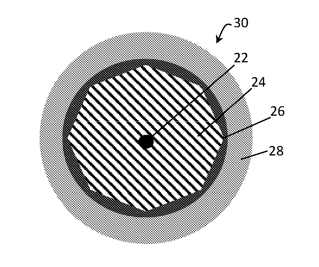
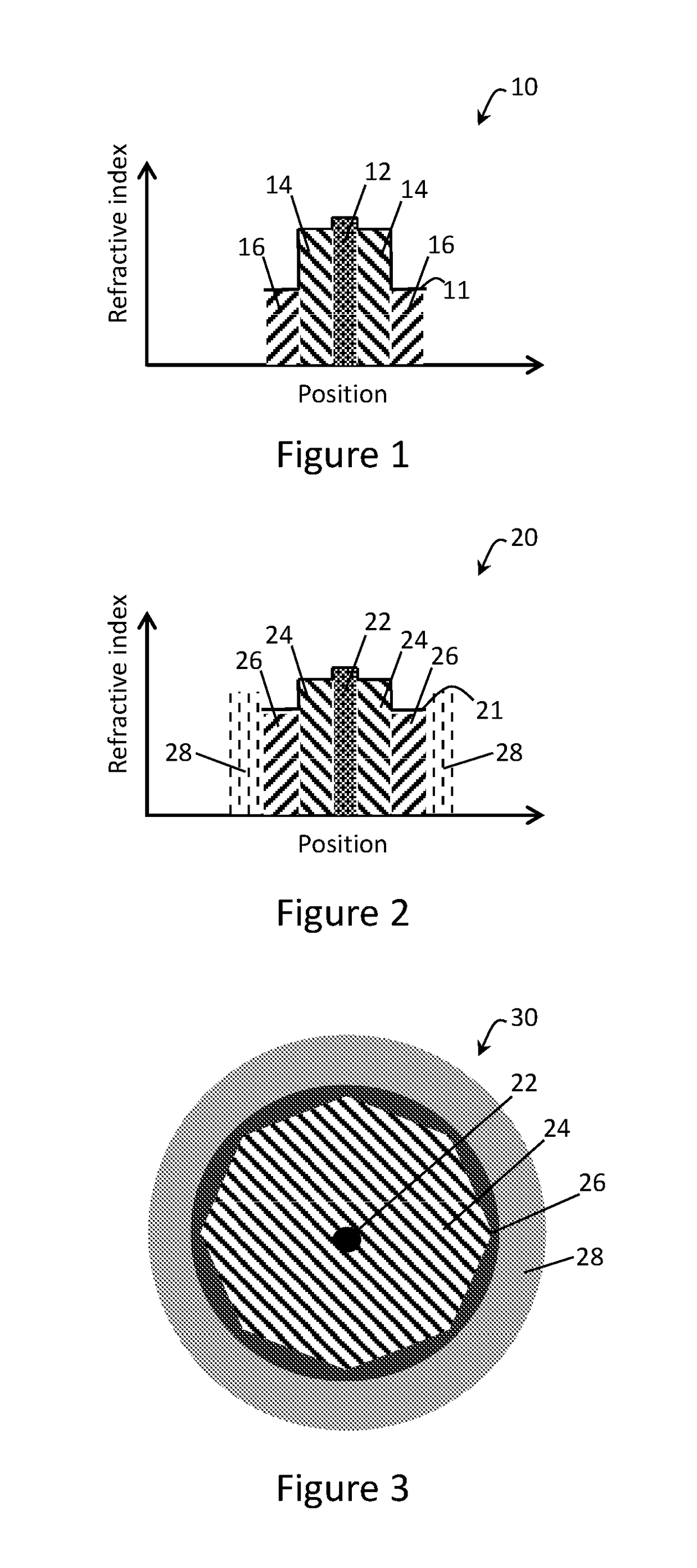
[0040]According to an embodiment of the present invention, there is provided an active optical fibre 30, as shown in FIG. 3, with relative refractive indexes of components of the active optical fibre 30 shown in the graphical representation 20 of the active optical fibre 30. Indeed, in FIG. 2, it can be seen that the active optical fibre 30 includes components having different refractive indexes shown by the line 21 relative to their position in the optical fibre 30.

[0041]The active optical fibre 30 includes a central core 22 comprised of a first material with a first refractive index. For example, in an embodiment, the first material is Ytterbium doped silica material with a refractive index of 1.452. Immediately surrounding the core 22 is an inner cladding 24 comprised of a second material with a second refractive index. In the embodiment, the second material is pure silica with a refractive index of 1.45. The core 22 and the inner cladding 24 form an area configured to propagate ...


PUM

PropertyMeasurementUnit
operating temperatureaaaaaaaaaa
thermal conductivityaaaaaaaaaa

Abstract

An active optical fibre, including: a core; an inner cladding substantially surrounding the core, whereby the core and the inner cladding form an area configured to propagate pump radiation; an outer cladding comprised of at least a third material with at least a third refractive index substantially surrounding the inner cladding, the third refractive index being smaller than the second refractive index, whereby the outer cladding confines pump radiation to the core and the inner cladding; and a coating comprised of a thermally conductive material substantially surrounding the outer cladding, wherein the inner cladding is configured to reduce impact of spatial hole-burning on absorption of the pump radiation as the pump radiation propagates through the active optical fibre, and wherein the thermally conductive material of the coating supports a reduced temperature increase between the area and an outer surface of the coating.

Description

TECHNICAL FIELD[0001]The present invention relates to an active optical fibre including a core, an inner cladding, an outer cladding, and a coating comprised of a thermally conductive metal, graphite or other material substantially surrounding the outer cladding. Particularly, but not exclusively, the inner cladding is configured to reduce impact of spatial hole-burning on absorption of pump radiation as the pump radiation propagates through a length of the active optical fibre, and the thermally conductive metal, graphite or other material of the coating, such as Aluminium, supports a reduced temperature increase between an area including the core and the inner cladding of the optical fibre and an outer surface of the coating via the coating and the outer cladding.BACKGROUND OF INVENTION[0002]Currently, most existing active, double clad optical fibres utilise a low refractive index polymer cladding for coating the optical fibre. These existing double clad fibres have a core and an ...

Claims


Application Information

Patent Timeline
Patent Type & Authority Applications(United States)
IPC IPC(8): H01S3/04C03C25/42H01S3/094C03C3/04H01S3/067
CPCH01S3/0405C03C3/04H01S3/06716H01S3/06733H01S3/094003C03C25/42G02B6/03633G02B6/0365G02B6/03694G02B6/02395C03C3/06C03C13/045C03C2201/02C03C2201/12C03C2201/14C03C2201/3488C03C25/1063H01S3/067H01S3/06754
Inventor DANIEL, JAECLARKSON, ANDREW W.SIMAKOV, NIKITA
Owner COMMONWEALTH OF AUSTRALIA REPRESENTED BY DEPT OF DEFENCE DEFENCE SCI & TECH ORG
Why Eureka
Try Eureka