Stamping press arrangement

a stamping press and arrangement technology, applied in the field of stamping press arrangement, can solve the problems of affecting the possibility of optimizing the entire process, low precision, and weak structure, and achieve the effects of reducing effort, simple and inexpensive drive mechanism, and few moving parts

Inactive Publication Date: 2018-02-01
BRUDERER ARBON SCHWEIZ
View PDF4 Cites 4 Cited by
  • Summary
  • Abstract
  • Description
  • Claims
  • Application Information

AI Technical Summary

Benefits of technology

[0037]In order to design the system concept of the stamping press arrangement according to the invention as robust and failsafe as possible and to reduce the effort with respect to technical implementation to a minimum, it is further advantageous that the stamping press arrangement only has precisely one flywheel, precisely one friction and precisely one brake in the drive train for the stamping press units.
[0038]In a further preferred embodiment of the stamping press arrangement, the first stamping press units and / or the at least one second stamping press unit have each precisely one connecting rod, by means of which the stamping force is introduced centrally into the respective press ram. This way of construction is advantageous particularly in case of short press rams, seen in transport direction, or in case of substantially central press ram load, respectively, because it has a simple and inexpensive drive mechanism with few moving parts.
[0039]In a further preferred embodiment of the stamping press arrangement, the first stamping press units and / or the at least one second stamping press unit have each two connecting rods, by means of which the stamping force is introduced symmetrically into the respective press ram. This way of construction is advantageous particularly in case of relatively long press rams, seen in transport direction, or in case of relatively asymmetric press ram load, respectively, because it increases the tilt resistance of the press ram.
[0040]It is further advantageous that each one of the stamping press units of the stamping press arrangement has an own mass compensation device. In this way, the dynamic forces acting towards the outside can be diminished or eliminated, respectively.
[0041]It is also advantageous that each one of the stamping press units of the stamping press arrangement is adjustable independently from the other stamping press units with respect to press ram stroke and / or closing height. In this way, the stamping press arrangement according to the invention provides a maximum of production flexibility and production precision.

Problems solved by technology

This stamping press has the disadvantage that it is structurally weak and therefore only provides low precision as well as allows only comparatively slow stroke speeds.
Additionally, the top press part, which produces the pull-off tabs, has mandatorily the same stroke like the bottom press part, which processes the lids, such that the influencing possibilities for optimizing the entire process are considerably restricted.
This stamping press has the disadvantage that it has a complicated construction with three different press rams and that it is also structurally weak, such that also in this case it allows only a low precision as well as only comparatively slow stroke speeds.
A particular disadvantage of this construction is additionally that deformations of the one press half due to stamping force and / or temperature have a strong influence on the respective other press half.
This stamping press avoids some of the disadvantages of the stamping presses mentioned above, it has however still the disadvantage that the press ram of the first press is relatively big and accordingly massive, which leads to enormous component stress and a high energy consumption in case of high stroke speeds or significantly limits the potential for increasing the stroke speeds and consequently for increasing the productivity of the press, respectively.
Additionally, due to the use of a common tool for three shell rows the problem results that the first press has to be operated with an enormous press load in order to ensure a precise carving depth for all three shell rows, thus requiring much energy and being prone to wear.
This stamping press partially avoids the disadvantages of the above mentioned stamping press, however it has the disadvantage that it is constructed in a very complex way and has many wear-prone and energy consuming components, therefore having a negative influence on its energy efficiency, its life, its maintenance intensity and last but not least also on the attainable stroke speeds.

Method used


Image

  • Stamping press arrangement
  • Stamping press arrangement
  • Stamping press arrangement

Examples


Embodiment Construction

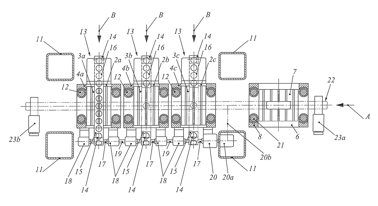
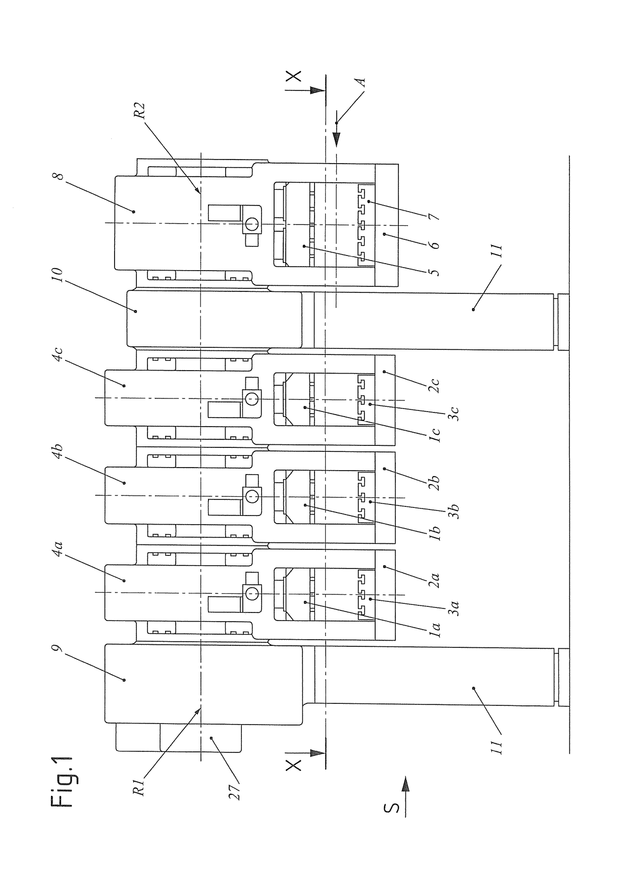
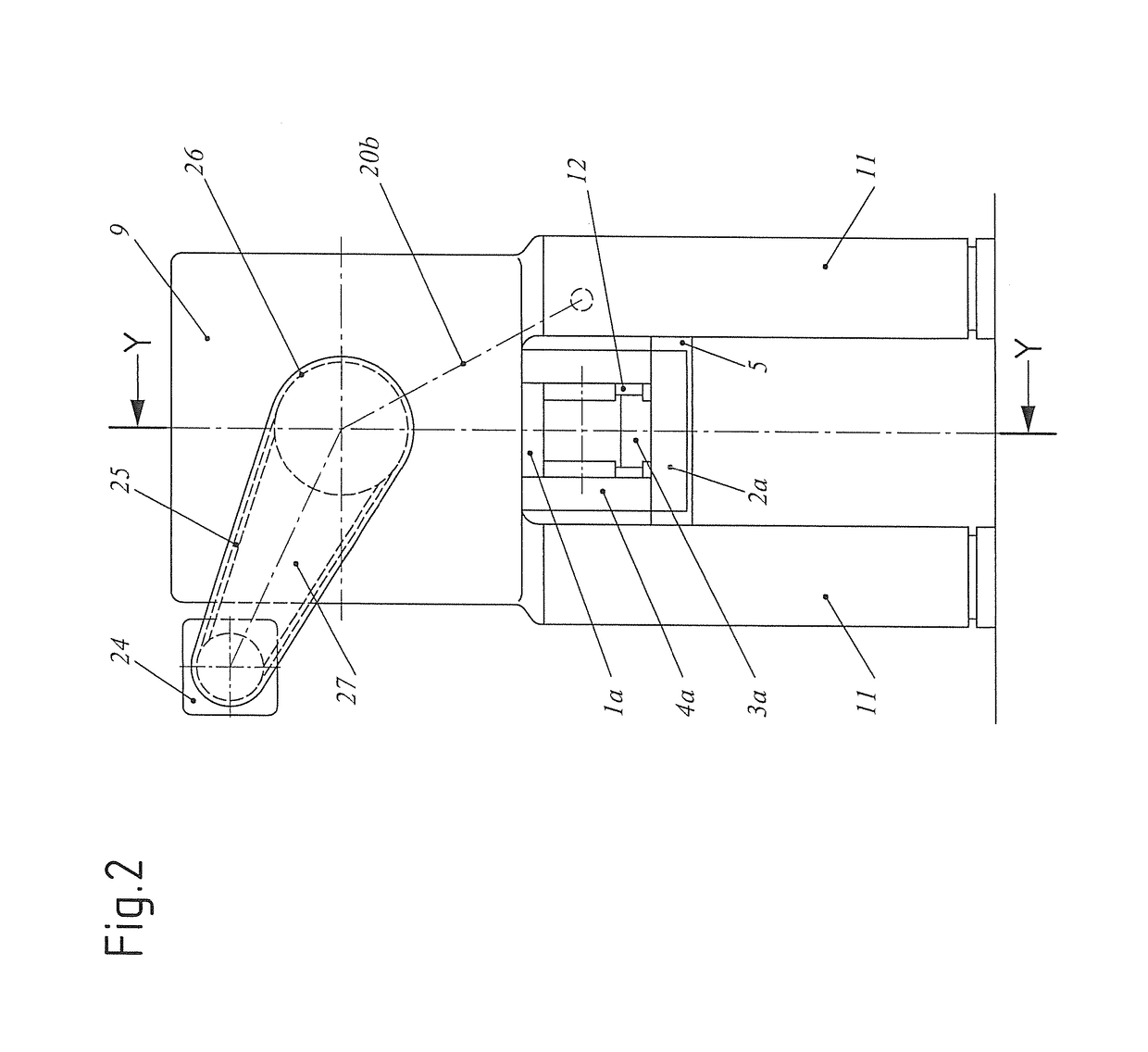
[0051]FIGS. 1 and 2 show a first stamping press arrangement for manufacturing metal container lids with a push-in or a pull-off tab and which can be opened without tools, once in a front view (FIG. 1) and once in a side view with viewing direction S from the left (FIG. 2).

[0052]As can be seen by viewing together with FIGS. 3 and 4, which show a horizontal section along the line X-X of FIG. 1 (FIG. 3) and a partial vertical section along the line Y-Y of FIG. 2 (FIG. 4) through the press arrangement, the latter comprises three adjacent stamping presses 4a, 4b, 4c (three first stamping press units according to the invention), in the following called “conversion-presses”, by means of which prefabricated metal sheet lids are provides with different profiles, with a carving for the opening location as well as with an additionally supplied push-in or pull-off tab, respectively. The three conversion presses 4a, 4b, 4c are coupled to one another as common self-supporting structure 4a-4c. The...


PUM

PropertyMeasurementUnit
frictionaaaaaaaaaa
stamping forceaaaaaaaaaa
dynamic forcesaaaaaaaaaa

Abstract

The invention relates to a stamping press arrangement comprising a plurality of first stamping press units arranged adjacent to one another, which have working directions extending parallel in relation to each other in a common plane, and comprising a second stamping press unit, the working direction of which extends perpendicularly in relation to the working directions of the first stamping press units, such that material processed in said stamping press unit can be guided in the direct extension of the working direction thereof into the working regions of the first stamping press units. The stamping press units each have a crankshaft portion or eccentric shaft portion, by means of which the travel movement of the press ram is effected via a connecting rod. The crankshaft portion or eccentric shaft portion of the first stamping press units are driven forcibly together via a common drive unit with the same speed and comprise a common axis of rotation. The crankshaft portion or eccentric shaft portion of the stamping press unit is coupled to the crankshaft portion or eccentric shaft portion of the first stamping press units so as to forcibly rotate therewith in a synchronous manner. The invention allows high-precision and high-speed stamping press arrangements to be provided for economically mass-producing multi-part stamping and shaped and punched products which have low tolerances, such as container ends with press-in or pull tabs for opening without tools, in a cost-effective manner.

Description

CROSS-REFERENCE TO RELATED APPLICATION[0001]This application is a National Stage application of International Patent Application No. PCT / CH2015 / 000018, filed on Feb. 11, 2015, which is hereby incorporated by reference in its entirety.TECHNICAL FIELD OF THE INVENTION[0002]The present invention relates to a stamping press arrangement as well as to a use of the stamping press arrangement according to the preambles of the independent claims.BACKGROUND[0003]A variety of components are manufactured by stamping presses in a particularly economic way and in large numbers.[0004]A special field is the manufacturing of container lids with a push-in or a pull-off tab which can be opened without tools, also called EOE (Easy Open Can Ends) by the industry, for which manufacturing pre-fabricated metal sheet lids are provided in the stamping press, with different profiles, with a carving for the opening position as well as with a separately supplied push-in or a pull-off tab.[0005]U.S. Pat. No. 4,1...

Claims


Application Information

Patent Timeline
Patent Type & Authority Applications(United States)
IPC IPC(8): B21D51/38B21D35/00B21D22/02
CPCB21D51/383B21D22/02B21D35/002B30B15/0064
Inventor HAFNER, JOSEF THOMAS
Owner BRUDERER ARBON SCHWEIZ
Why Eureka
Try Eureka