Light source unit, illuminator, and projector

a technology of light source unit and illuminator, which is applied in the direction of lighting and heating apparatus, semiconductor devices of light sources, instruments, etc., can solve the problem of insufficient uniformity of illuminance distribution on phosphor

Active Publication Date: 2018-02-01
SEIKO EPSON CORP
View PDF6 Cites 5 Cited by
  • Summary
  • Abstract
  • Description
  • Claims
  • Application Information

AI Technical Summary

Benefits of technology

[0015]According to the configuration described above, the projector, which includes

Problems solved by technology

In the configuration described above, however, the uniformity of the illuminance distribution

Method used


Image

  • Light source unit, illuminator, and projector
  • Light source unit, illuminator, and projector
  • Light source unit, illuminator, and projector

Examples


first embodiment

[0029]A first embodiment of the invention will be described below in detail with reference to the drawings.

[0030]In the drawings used in the following description, a characteristic portion is enlarged for convenience in some cases for clarity of the characteristic thereof, and the dimension ratio and other factors of each component are therefore not always equal to actual values.

Projector

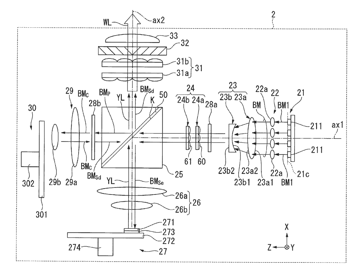
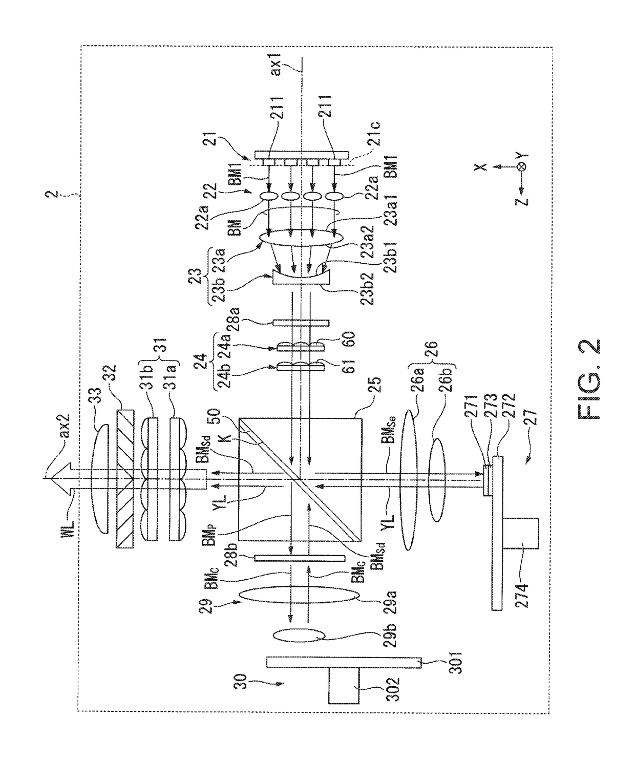
[0031]A projector according the present embodiment is a projection-type image display apparatus that displays color video images on a screen (surface on which images are projected). The projector includes three liquid crystal light modulators corresponding to respective color light: red light, green light, and blue light. The projector further includes laser diodes, each of which produces high-luminance, high-intensity light, as a light source of an illuminator.

[0032]FIG. 1 is a schematic configuration diagram showing the optical system of the projector according to the present embodiment.

[0033]A pr...

second embodiment

[0103]A second embodiment of the invention will be described below with reference to FIGS. 7 to 11.

[0104]The basic configurations of a projector and an illuminator according to the second embodiment are the same as those in the first embodiment, but the second embodiment differs from the first embodiment in terms of the positional relationship between the principal rays of the light beams and the optical axes of the lenslets of the first fly-eye lens. In the second embodiment, no description of the configurations of the projector and the illuminator will therefore be made.

[0105]FIG. 7 shows an example of the positional relationship in the illuminator according to the second embodiment between the principal rays of a plurality of light beams and the optical axes of a plurality of lenslets of the first fly-eye lens. FIG. 7 corresponds to FIG. 6 in the first embodiment and is an enlarged view of the lenslets in part of the first fly-eye lens. Also in the present embodiment, the light s...


PUM


Abstract

A light source unit includes one or more light source rows that include a first light source row including light emitting devices. The light emitting devices of the first light source rows are arranged at non-uniform intervals. An illuminator includes a light source unit for emitting a bundle of light beams, a first fly-eye lens including lenslets, a second fly-eye lens, and a condenser lens. The light source unit includes one or more light source rows each including light emitting devices. The principal rays of first light beams outputted from a first light source row out of the one or more light source rows enter different lenslets out of the lenslets. A positional relationship between a principal ray of each of the first light beams and the optical axis of the lenslet which the principal ray enters is aperiodic over the first light source row.

Description

BACKGROUND1. Technical Field[0001]The present invention relates to a light source unit, an illuminator, and a projector.2. Related Art[0002]As an illuminator used, for example, in a projector, an illuminator using a solid state light source, such as a semiconductor laser, has been proposed. JP-A-2012-118302 discloses an illuminator including a solid-state light source group formed of a plurality of solid-state light sources, a collimator lens group formed of a plurality of collimator lenses that parallelize light beams from the plurality of solid-state light sources, a first reflector and a second reflector that reflect the light beams through the collimator lens group, a light collection system that collects the light beams from the second reflector, and a homogenizer system that homogenizes the intensity distribution of the light through the light collection system.[0003]In the illuminator disclosed in JP-A-2012-118302, the light beams from the plurality of solid-state light sourc...

Claims


Application Information

Patent Timeline
IPC IPC(8): G03B21/20F21V5/00F21V13/06G02B19/00
CPCG03B21/208G02B19/0057G02B19/0009G03B21/2013G03B21/2066F21Y2115/30F21V5/008F21V13/06G03B21/204G03B33/12F21V5/007H04N9/3152H04N9/3161H04N9/3164
Inventor YASUMATSU, WATARUEGAWA, AKIRA
Owner SEIKO EPSON CORP
Why Eureka
Try Eureka