Multilayer ceramic electronic component

a technology of electronic components and ceramics, applied in the direction of fixed capacitors, stacked capacitors, fixed capacitor details, etc., can solve the problems of multilayer ceramic capacitor damage or breakage of joints, board bends and deformities, stress can similarly occur, etc., to reduce tensile stress on e-dimensional end portions, prevent cracking, and ensure sealability

Active Publication Date: 2018-02-01
MURATA MFG CO LTD
View PDF4 Cites 20 Cited by
  • Summary
  • Abstract
  • Description
  • Claims
  • Application Information

AI Technical Summary

Benefits of technology

[0012]According to a multilayer ceramic electronic component of a preferred embodiment of the present invention, since the first and the second external electrodes are disposed only on the first and the second end surfaces, it becomes possible to reduce the tensile stress on an e-dimensional end portion due to reduction in the total volume of the first and the second external electrodes (the base electrode layer and the plating layer), and it is possible to prevent occurrence of cracking from the e-dimensional end portion of the external electrodes.
[0013]Also, according to a multilayer ceramic electronic component of a preferred embodiment of the present invention, since the first and the second external electrodes include a portion having a thickness larger than the thickness of the center portion of the first and the second end surfaces in the peripheries of the first and the second end surfaces in planar view from the direction linking the first and the second end surfaces, it is possible to ensure the thickness of the first and the second external electrodes in corner portions of the laminate, and thus it is possible to ensure the sealability of the first and the second external electrodes to the laminate.
[0014]Further, according to a multilayer ceramic electronic component of a preferred embodiment of the present invention, since the first metal terminal connected with the first external electrode, and the second metal terminal connected with the second external electrode have a terminal joint portion connected with each external electrode, an extended portion connected with the terminal joint portion and extending in the direction of a mou

Problems solved by technology

However, when a multilayer ceramic capacitor is directly mounted by a solder on a mounting board, the mounting board on which the multilayer ceramic capacitor is mounted and the multilayer ceramic capacitor expand or contract according to the respective coefficients of thermal expansion when the temperature changes, and the difference in coefficient of thermal expansion between these elements causes a stress that leads, for example, the dam

Method used


Image

  • Multilayer ceramic electronic component
  • Multilayer ceramic electronic component
  • Multilayer ceramic electronic component

Examples


first preferred embodiment

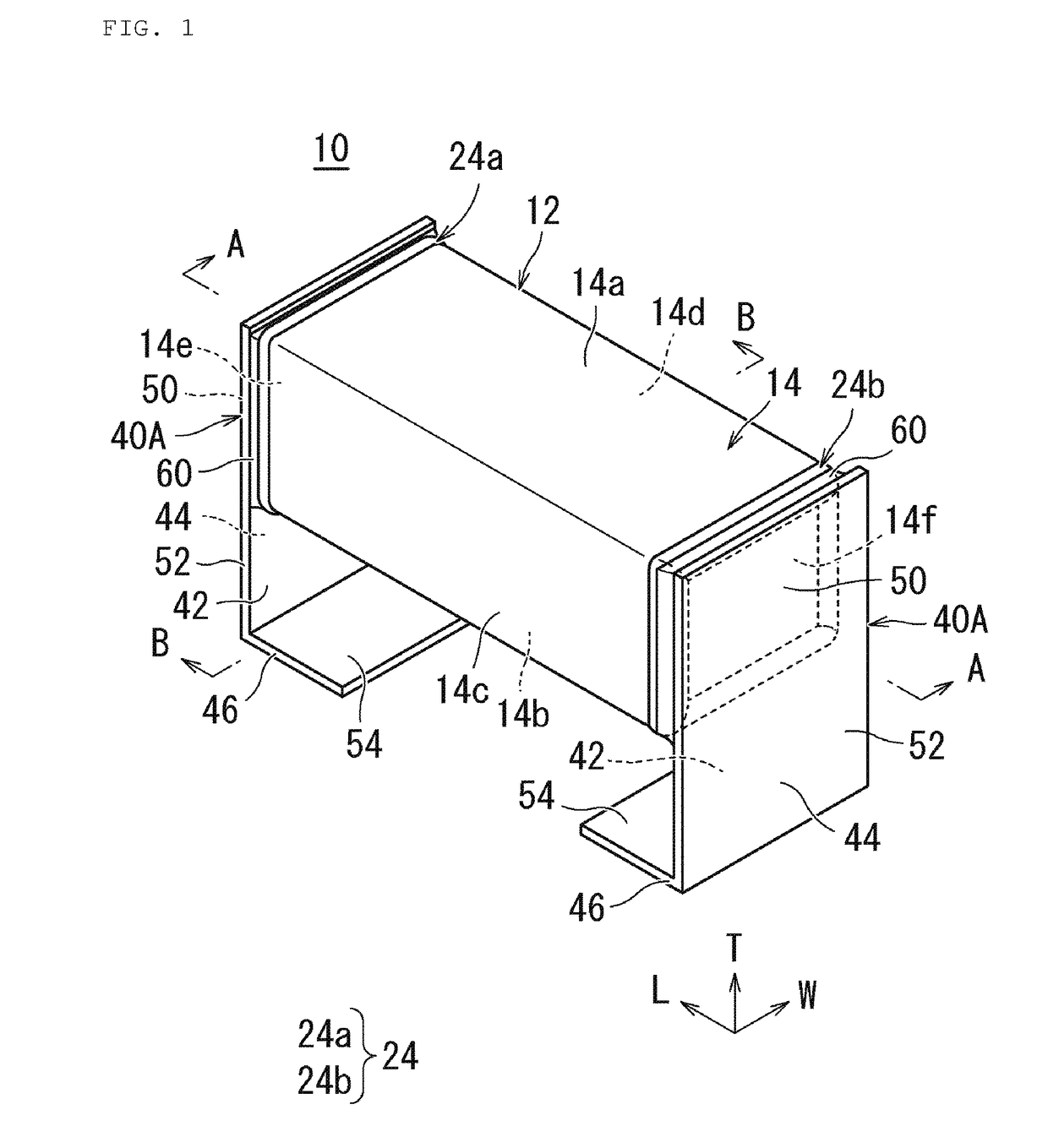
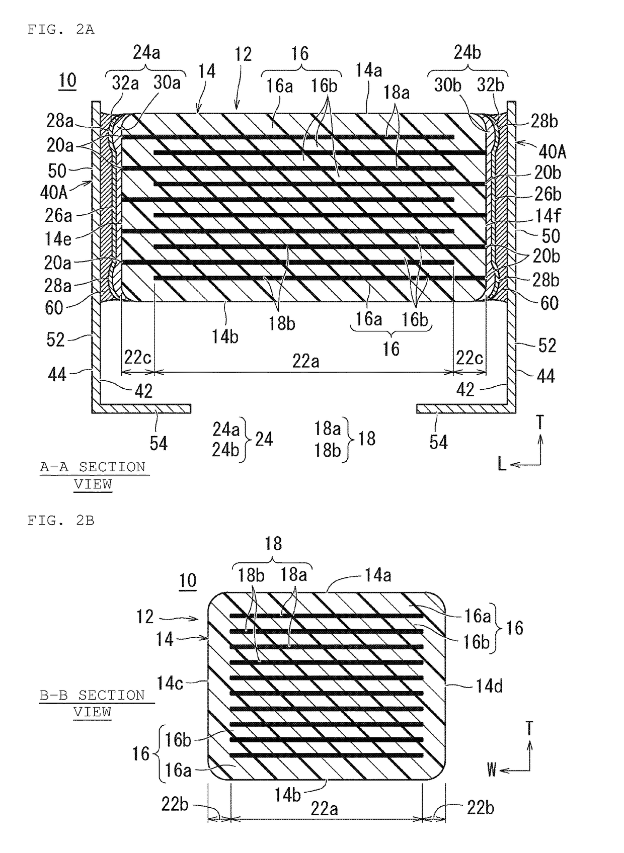
[0031]A multilayer ceramic electronic component according to the first preferred embodiment of the present invention will be described. FIG. 1 is an external perspective view showing one example of a multilayer ceramic electronic component according to the first preferred embodiment of the present invention. FIG. 2A is a section view taken along A-A of FIG. 1 showing the multilayer ceramic electronic component according to the first preferred embodiment of the present invention, and FIG. 2B is a section view taken along B-B of FIG. 1 showing the multilayer ceramic electronic component according to the first preferred embodiment of the present invention. FIG. 3A is an external perspective view showing one example of an electronic component body of the multilayer ceramic electronic component according to the first preferred embodiment of the present invention, and FIG. 3B illustrates an external electrode when the electronic component body of the multilayer ceramic electronic componen...

second preferred embodiment

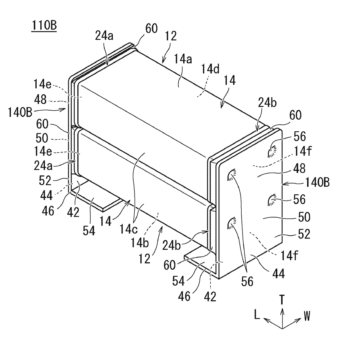
[0104]A multilayer ceramic electronic component according to the second preferred embodiment of the present invention will be described. FIG. 8 is an external perspective view showing one example of a multilayer ceramic electronic component according to the second preferred embodiment of the present invention. FIG. 9A is a section view taken along C-C of FIG. 8 showing a multilayer ceramic electronic component according to the second preferred embodiment of the present invention, and FIG. 9B is a section view taken along D-D of FIG. 8 showing the multilayer ceramic electronic component according to the second preferred embodiment of the present invention. A multilayer ceramic electronic component 110A according to this preferred embodiment has the same configuration as the multilayer ceramic electronic component 10 described with reference to FIG. 1 except that a pair of metal terminals 140A is of the type that sandwiches the two electronic component bodies 12 stacked in the vertica...


PUM

PropertyMeasurementUnit
Thicknessaaaaaaaaaa
Thicknessaaaaaaaaaa
Thicknessaaaaaaaaaa

Abstract

A multilayer ceramic electronic component includes an electronic component body including a laminate and an external electrode, and a pair of metal terminals that are joined by a joining material. The pair of metal terminals includes a terminal joint portion, an extended portion and a mounting portion. The external electrode is provided only on both end surfaces of the laminate, and includes first and second external electrodes. The first external electrode and the second external electrode each include a saddle portion with a thickness larger than the thickness of a center portion of each end surface in the periphery of the first end surface and the second end surface of the laminate, respectively.

Description

CROSS REFERENCE TO RELATED APPLICATIONS[0001]This application claims the benefit of priority to Japanese Patent Application No. 2016-147598 filed on Jul. 27, 2016. The entire contents of this application are hereby incorporated herein by reference.BACKGROUND OF THE INVENTION1. Field of the Invention[0002]The present invention relates to a multilayer ceramic electronic component including, for example, a multilayer ceramic capacitor or the like.2. Description of the Related Art[0003]In recent years, a multilayer ceramic capacitor (electronic component body) which is a chip-type electronic component made of ceramic has been commonly used. However, when a multilayer ceramic capacitor is directly mounted by a solder on a mounting board, the mounting board on which the multilayer ceramic capacitor is mounted and the multilayer ceramic capacitor expand or contract according to the respective coefficients of thermal expansion when the temperature changes, and the difference in coefficient ...

Claims


Application Information

Patent Timeline
IPC IPC(8): H01G4/30H01G4/012H01G4/248H01F1/34H01L41/047H01L41/083H01C7/00H01G4/12H01L41/187
CPCH01G4/30H01G4/1227H01G4/012H01G4/248H01F1/34H01L41/0471H01L41/0472H01L41/083H01C7/008H01L41/1876H01F17/0013H01F27/292H01C7/003H01C7/18H01G4/12H01G4/232H01G4/2325H10N30/877H10N30/50H10N30/871H10N30/872H10N30/8554
Inventor ITAMOCHI, MASAKAZU
Owner MURATA MFG CO LTD
Why Eureka
Try Eureka