Battery device

a battery cell and battery technology, applied in the field of battery cells, can solve the problems of reducing the cooling liquid contained in the cooling elements, the inability of the cooling elements to absorb the cooling liquid retained in the battery case efficiently, and the inability to smoothly guide the gas produced by the cooling element, etc., to suppress the decrease in the cooling efficiency of the battery cell, the effect of reducing the weight of the battery cell

Active Publication Date: 2018-02-01
IKUYO +1
View PDF3 Cites 19 Cited by
  • Summary
  • Abstract
  • Description
  • Claims
  • Application Information

AI Technical Summary

Benefits of technology

[0004]In the conventional technique as described in International Publication No. WO2011 / 105256, since the cooling elements are filled between the adjacent battery cells, and between the battery cells and the battery case, it may not be possible to smoothly guide the gas (coolant steam) produced by evaporation of the cooling liquid of the cooling elements to the outside of the cooling elements. That is, the coolant steam may be retained inside the cooling elements. Under the circumstances, it becomes impossible for the cooling elements to absorb the cooling liquid retained in the battery case efficiently. Since the quantity of the cooling liquid contained in the cooling elements is reduced, the cooling efficiency may be lowered undesirably.
[0005]The present invention has been made in consideration of the above problems, and an object of the present invention is to provide a battery apparatus in which it is possible to achieve weight reduction, and suppress the decrease in the cooling efficiency of a battery cell by the evaporation latent heat of cooling liquid of a cooling element.

Problems solved by technology

WO2011 / 105256, since the cooling elements are filled between the adjacent battery cells, and between the battery cells and the battery case, it may not be possible to smoothly guide the gas (coolant steam) produced by evaporation of the cooling liquid of the cooling elements to the outside of the cooling elements.
Under the circumstances, it becomes impossible for the cooling elements to absorb the cooling liquid retained in the battery case efficiently.
Since the quantity of the cooling liquid contained in the cooling elements is reduced, the cooling efficiency may be lowered undesirably.

Method used


Image

  • Battery device
  • Battery device
  • Battery device

Examples


first embodiment

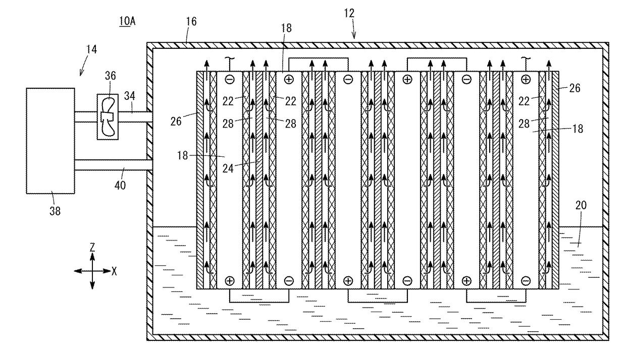
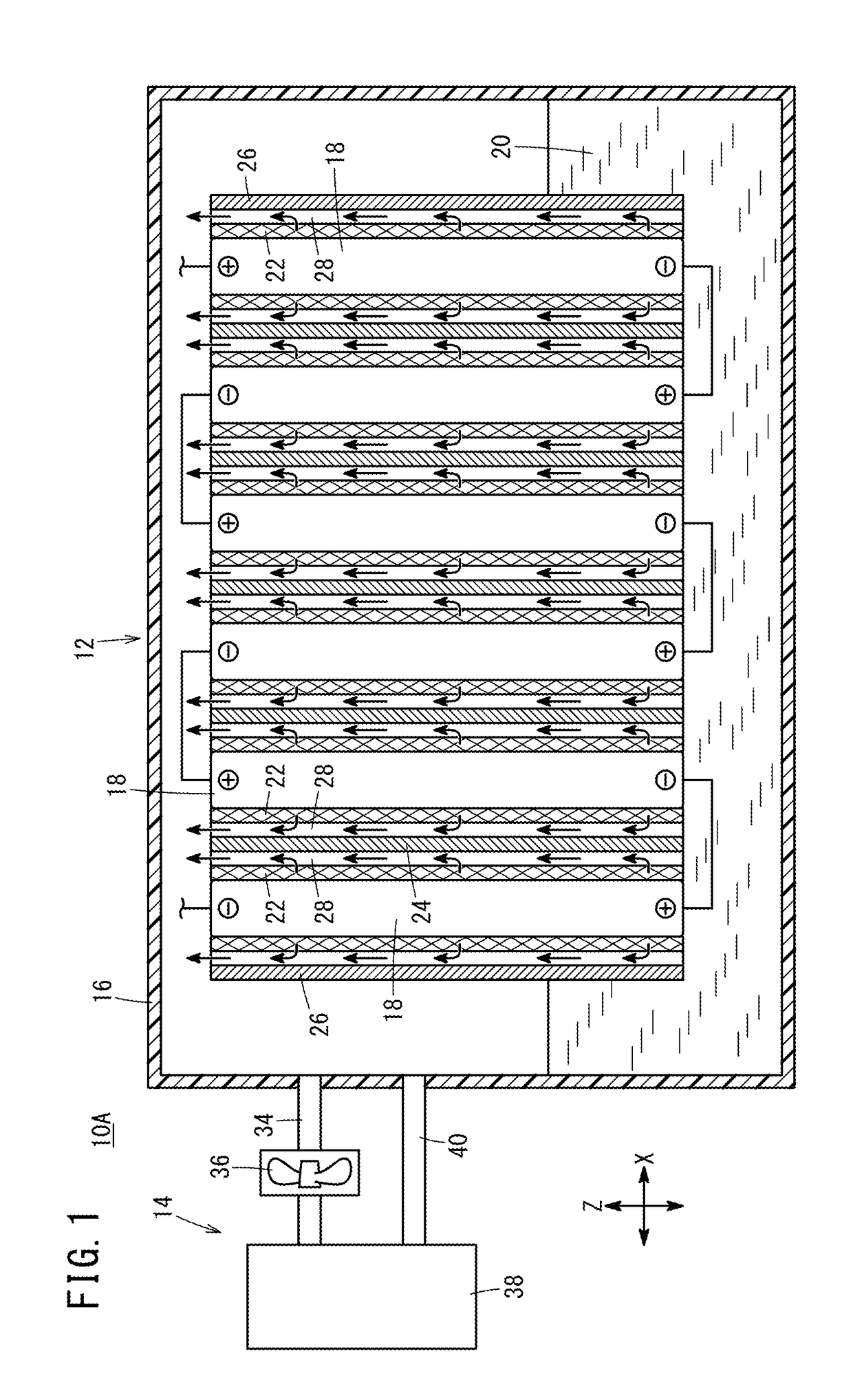
[0029]A battery apparatus 10A according to an embodiment of the present invention is mounted in an electric vehicle such as an electric automobile, a hybrid automobile equipped with an internal combustion engine, and a fuel cell automobile equipped with a fuel cell. That is, the battery apparatus 10A is capable of charging electrical energy supplied from a power feeding apparatus, and capable of supplying electrical energy to an electric motor for driving the vehicle. However, the battery apparatus 10A is not limited to an example where the battery apparatus 10A is mounted on such an electric vehicle. The battery apparatus 10A can be utilized in combination with any apparatuses.

[0030]As shown in FIG. 1, the battery apparatus 10A includes a battery body 12 and a battery heat exchanger 14 provided for the battery body 12. The battery body 12 includes a battery case 16 having a rectangular parallelepiped shape, and a plurality battery cells 18 provided in parallel within the battery ca...

second embodiment

[0061]Next, the battery apparatus 10B according to the second embodiment of the present invention will be described with reference to FIG. 4. In the battery apparatus 10B according to the second embodiment, the constituent components having the same or similar functions and advantages as or to that of the battery apparatus 10A according to the first embodiment are labeled with the same reference numerals, and detailed description is omitted. Also in a battery apparatus 10C according to a third embodiment, the constituent components having the same or similar functions and advantages as or to that of the battery apparatus 10A according to the first embodiment are labeled with the same reference numerals, and detailed description is omitted.

[0062]As shown in FIG. 4, the battery apparatus 10B according to the embodiment of the present invention further includes a liquid holder member 42 impregnated with cooling liquid 20. For example, the liquid holder member 42 may be an open cell foa...

third embodiment

[0064]Next, the battery apparatus 10C according to the third embodiment of the present invention will be described with reference to FIG. 5. As shown in FIG. 5, the battery apparatus 10C according to the embodiment of the present invention includes a battery body 44 and a heat exchanger 46. The battery body 44 includes a rectangular parallelepiped battery case 48. In the battery case 48, six battery cells 18 are arranged in a vertical direction indicated by an arrow Z in a state where the longitudinal direction of the battery cells 18 is oriented in a horizontal direction (the direction perpendicular to the paper surface in FIG. 5). The number of the battery cells 18 can be determined arbitrarily.

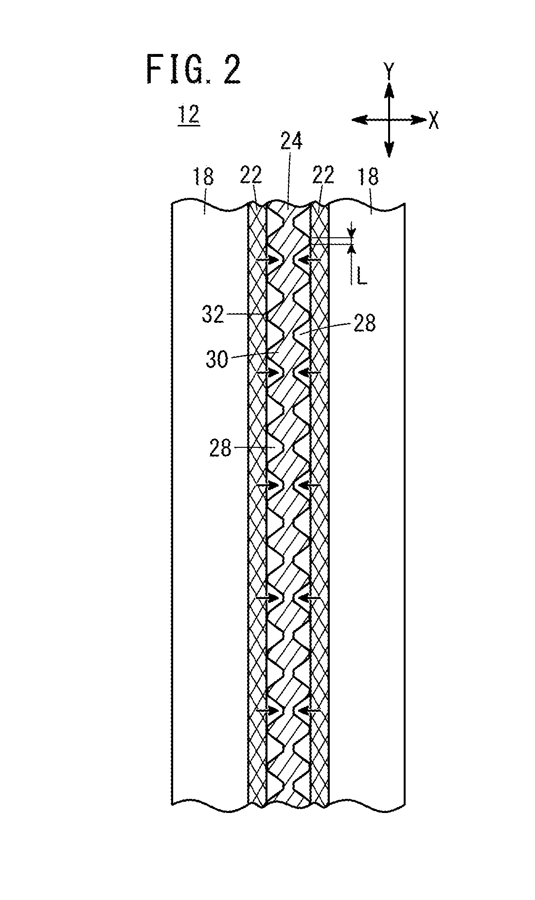
[0065]Further, the cooling elements 22 are provided on the outer surfaces on both sides of the battery cells 18. A spacer 24 is provided in each space between the adjacent cooling elements 22, and spacers 26 are provided outside the cooling elements 22 at the outermost positions. That is, t...


PUM

PropertyMeasurementUnit
boiling pointaaaaaaaaaa
evaporation latent heataaaaaaaaaa

Abstract

A battery device is provided with cooling bodies for contacting the outer surfaces of a plurality of battery cells arranged inside a battery case, and spacers provided adjacent to the cooling bodies. The cooling bodies absorb or are impregnated with a cooling fluid inside the battery case. Cooling medium vapor flow channels in which cooling medium vapor circulates are formed on the surfaces of the spacers facing the cooling bodies, the cooling medium vapor being generated by the evaporation of the cooling fluid of the cooling bodies.

Description

TECHNICAL FIELD[0001]The present invention relates to a battery apparatus (battery device) for cooling a plurality of battery cells mutually juxtaposed in a battery case, utilizing the evaporation latent heat of insulating cooling liquid.BACKGROUND ART[0002]Electric vehicles such as an electric automobile, a hybrid automobile equipped with an internal combustion engine, and a fuel cell automobile equipped with a fuel cell are equipped with a battery apparatus for supplying electrical energy to an electric motor for driving the vehicle. The battery apparatus of this type includes a plurality of battery cells that are connected in series electrically. These battery cells emit heat produced in chemical reactions at the time of charging and discharging of the battery cells. It is important to suppress the increase in the temperature of the battery cells, for maintaining the operation characteristics of the battery apparatus, and avoiding the decrease in the product life of the battery a...

Claims


Application Information

Patent Timeline
Patent Type & Authority Applications(United States)
IPC IPC(8): H01M10/613H01M10/66H01M10/6569H01M10/625H01M10/6555H01M50/204
CPCH01M10/613H01M10/625H01M10/6555H01M10/6569H01M10/66H01M2220/20H01M10/6551H01M10/647H01M10/6557Y02E60/10H01M50/204
Inventor TAJIMA, TAKAMITSUHIRANO, HIROKAZUSEKIGUCHI, TSUYOSHI
Owner IKUYO
Why Eureka
Try Eureka