
Imaging apparatus

a technology of x-ray apparatus and x-ray angle, which is applied in the field of x-ray apparatus, can solve the problems of reducing the total x-ray dose, affecting affecting the accuracy of the image, so as to reduce the sensitivity of the incident light or x-ray angle, the effect of high-speed signal processing and reducing the device temperatur

Inactive Publication Date: 2018-02-08
SHIZUKUISHI MAKOTO
View PDF3 Cites 0 Cited by
  • Summary
  • Abstract
  • Description
  • Claims
  • Application Information

AI Technical Summary

Benefits of technology

This configuration results in a more portable, cost-effective CT system with enhanced spatial and energy resolution, reduced X-ray dose, and lower maintenance needs, capable of high-speed 3D imaging with improved image quality and reduced environmental sensitivity.

Problems solved by technology

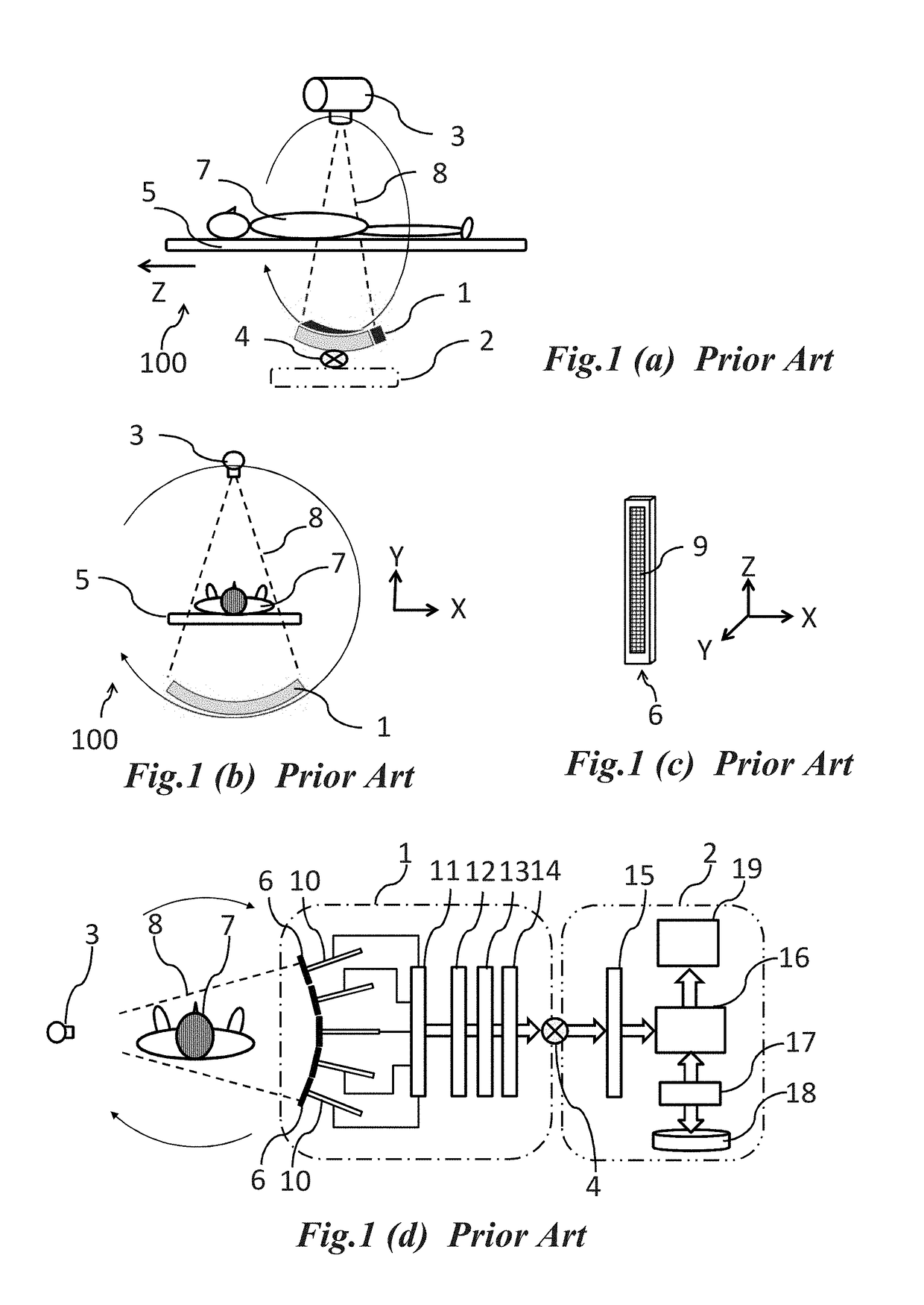
The pixel array 9, however, has a flat surface formed on a silicon substrate, and it may be difficult or, alternatively, impossible to have a smooth curved surface to oppose a fan beam X-ray in the direction of the rotation in the X-Y plane.
Further, with an increase in the pixel or slice number of the image sensor 6 in the direction of Z-axis, the cone angle of X-ray also increases, which may degrade image quality due to an artifact caused by the X-ray attenuations with different incident X-ray angles to the flat surface of the pixel array 9.
Otherwise, it may be difficult to reduce total X-ray dose, especially human exposure.
As a result, efforts for downsizing, weight reduction and cost reduction of the CT system 100 may all be made more difficult by the above-referenced precision tools, in addition to other significant factors associated with at least some conventional systems like the CT system 100 including, for example, a large installation space, heavy maintenance loads, a large-scale regulated power supply, and a large-scale cooling system of the conventional CT system 100.
As a result, the pixel array 9 is located close to the chip side edges which are not flat or smooth, and have a lot of crystal defects due to a wafer dicing process.
Accordingly, the location of the pixel array 9 may affect the image quality because the photo-diodes and peripheral circuits are formed close to these edges, and thus, may be exposed to incoming contaminations of metal impurities or reactive chemicals, for example.

Method used


Image

  • Imaging apparatus
  • Imaging apparatus
  • Imaging apparatus

Examples


Embodiment Construction

[0058]Detailed example embodiments are disclosed herein. However, specific structural and functional details disclosed herein are merely representative for purposes of describing example embodiments. Example embodiments may, however, be embodied in many alternate forms and should not be construed as limited to only the embodiments set forth herein.

[0059]Accordingly, while example embodiments are capable of various modifications and alternative forms, embodiments thereof are shown by way of example in the drawings and will herein be described in detail. It should be understood, however, that there is no intent to limit example embodiments to the particular forms disclosed, but to the contrary, example embodiments are to cover all modifications, equivalents, and alternatives falling within the scope of example embodiments. Like numbers refer to like elements throughout the description of the figures.

[0060]It will be understood that, although the terms first, second, etc. may be used h...


PUM


Abstract

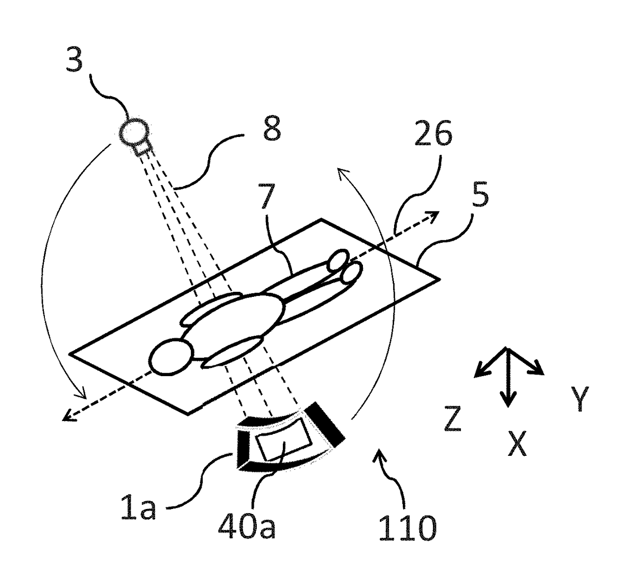
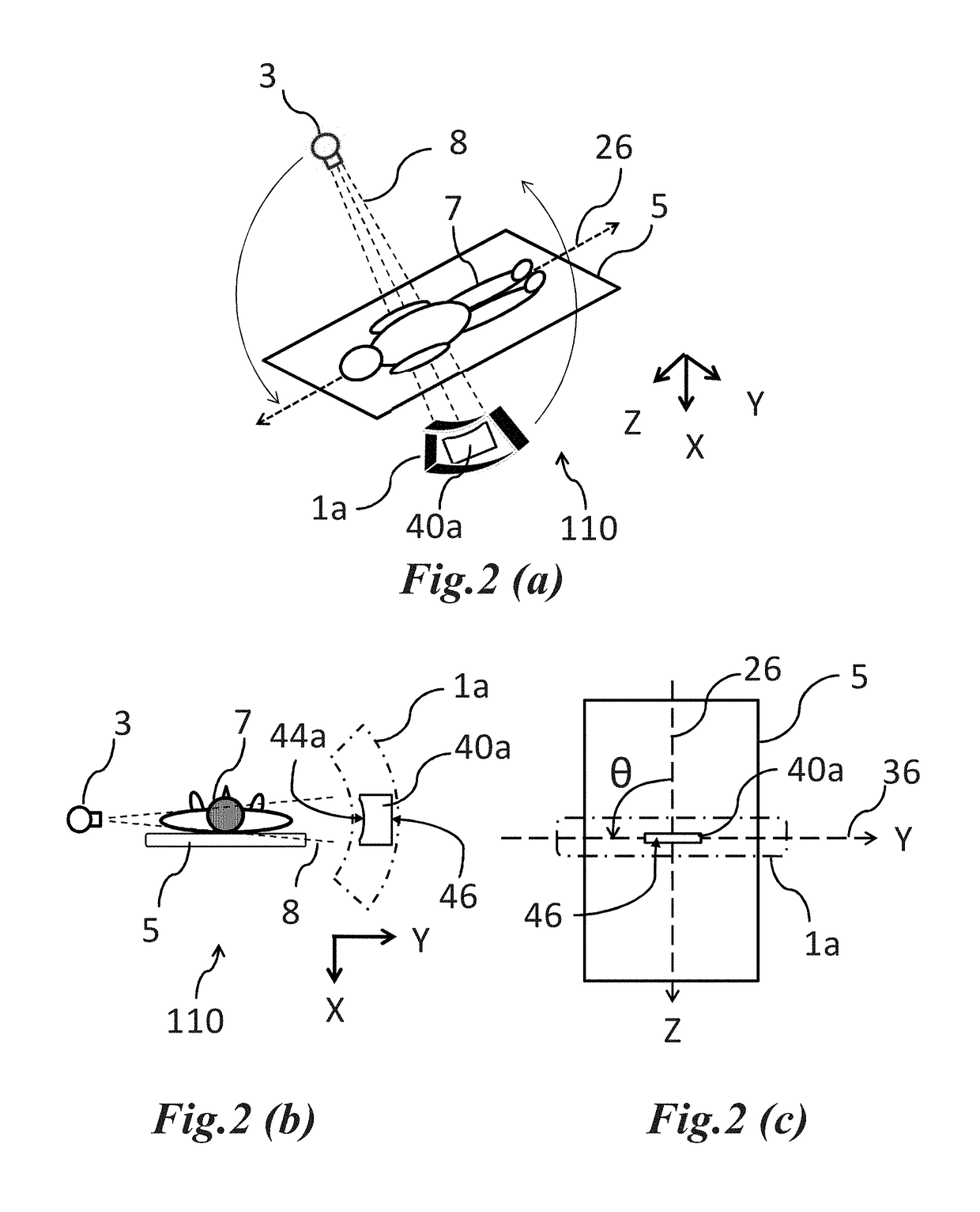
A tomographic imaging system includes a source configured to irradiate an object; a first image sensor including a first semiconductor substrate having a first face upon which a monolithic first pixel array is located; and a gantry configured to hold the first image sensor and rotate the image sensor around the object about a first rotation axis, the first pixel array including a first plurality of pixels configured to receive light that travels through or from the object based on the irradiation, the first plurality of pixels of the first pixel array being arranged in one or more rows and a plurality of columns such that, a total number of the one or more rows is less than a total number of the plurality of columns, and the one or more rows extend in a first direction, the first image sensor being arranged such that an angle between the first direction and a second direction is greater than 45 degrees and equal to or less than 90 degrees, the second direction being a direction parallel to the rotation axis or a direction in which the object moves during analysis of the object by the imaging system.

Description

CROSS-REFERENCE TO RELATED APPLICATION[0001]This U.S. non-provisional patent application is a divisional of U.S. application Ser. No. 14 / 963,568 filed on Dec. 9, 2015, which claims priority under 35 U.S.C. §119 to Japanese Patent Application No. 2015-195851 filed on Oct. 1, 2015, in the Japanese Patent Office (JPO), and Japanese Patent Application No. 2014-248934 filed on Dec. 9, 2014, in the JPO, the entire contents of each of which are incorporated herein by reference.BACKGROUND1. Technical Field[0002]Example embodiments relate to an imaging apparatus such as computed tomography enabling high spatial, timing and energy resolution with smaller form factor and lower power consumption.2. Related Art[0003]A computed tomographic (CT) system or, a CT system is now widely used for medical imaging and diagnostics. FIG. 1 (a) shows a conventional CT system 100. The CT system 100 includes an imaging unit 1 including a set of sensor elements and data acquisition systems (DAS), an X-ray sourc...

Claims


Application Information

Patent Timeline
Patent Type & Authority Applications(United States)
IPC IPC(8): A61B6/00A61B6/03
CPCA61B6/508A61B6/4417A61B6/4275A61B6/4233A61B6/032A61B6/4435A61B6/4028
Inventor SHIZUKUISHI, MAKOTO
Owner SHIZUKUISHI MAKOTO
Features
  • Generate Ideas
  • Intellectual Property
  • Life Sciences
  • Materials
  • Tech Scout
  • Unparalleled Data Quality
  • Higher Quality Content
  • 60% Fewer Hallucinations
Learn More