Eureka AIR delivers breakthrough ideas for toughest innovation challenges, trusted by R&D personnel around the world.

Plug and play with smart energy storage units

a technology of energy storage units and smart energy, applied in the direction of electrical storage systems, electrical circuits, ac network voltage adjustment, etc., can solve the problems of high cost, inconvenient control, and energy typically sent to ground, and achieves easy scaling, easy control, and simple integration

Active Publication Date: 2018-02-08
ORISON
View PDF4 Cites 25 Cited by
  • Summary
  • Abstract
  • Description
  • Claims
  • Application Information

AI Technical Summary

Benefits of technology

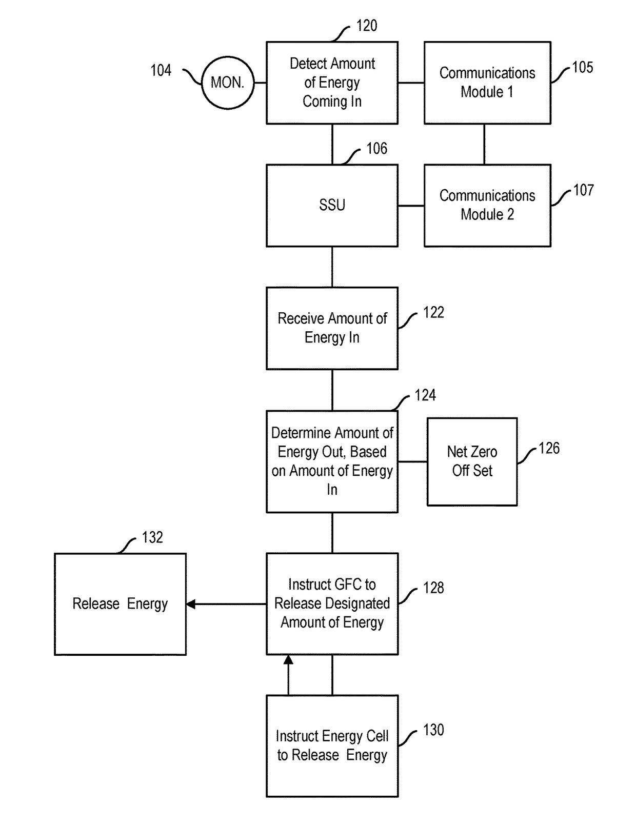
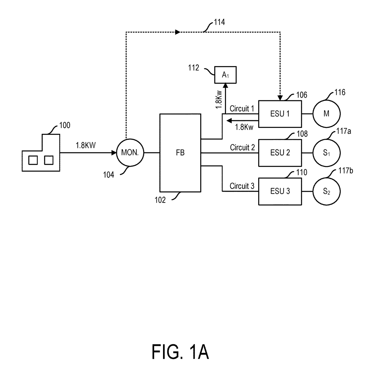
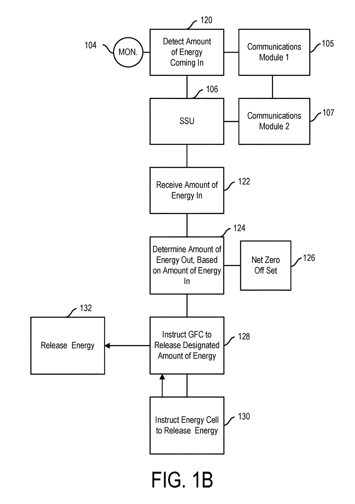
This patent describes a system of smart energy assets that can be easily connected to a local electric grid and used for energy storage and distribution. The smart energy storage units are designed to be plug-and-play, meaning they can be easily connected to the grid by simply plugging them into available outlets. The units are safe because they can only be charged when connected to the grid, and can be used for supplying energy to the grid. The system may also include sensors to monitor the condition of the grid, and can be connected to a remote command center, utility provider, or energy cloud for data transfer and connectivity. Overall, this patent provides a simple and efficient solution for integrating smart energy assets into local electric grids.

Problems solved by technology

For instance, commonly, where the over production of energy occurs, energy is typically sent to ground and therefore wasted.
However, due partly to the fact that the battery storage resides on the utility side of the meter, this model is very inefficient for batteries.
For instance, centralized battery storage only allows the utility system operators (e.g., generation, transmission, and / or distribution operators) to propagate several of the main issues with the grid, such as: congestion, inefficiency due to the separation between production and consumption, high costs, and long timelines due to large scale infrastructure and skilled resources and single use-case products.
Further, such battery systems are industrial sized, occupying huge warehouses of space.
Specifically, because of their large size the batteries themselves are difficult to control, and very hard to maintain.
It is easy for individual energy storage cells to become unbalanced, thus causing the battery as a whole to malfunction and / or suffer a diminution in capacity.
Further still, given the inefficiencies inherent to peaker plants, large-scale, industrial batteries cannot be offloaded as quickly as needed for them to act as a reserve.
Consequently, such batteries become fully charged and are not able to be fully discharged before they are needed to be charged again, and thus they have been found to be ineffectual at solving the problems they were designed to ameliorate.
Additionally, centralized battery storage only allows the DSO to react to demand events, that build up slowly, but change rapidly, requiring fine control that simply is not possible given the lack of control mechanisms to fluidly regulate the functioning of such large batteries.
Furthermore, such batteries store electricity at an overall loss due to conversion from AC (transmission) to DC (storage) and back again.
This loss is increased when transmission is also part of the equation.
And, to make matters worse, these industrialized batteries at best only marginally solve a small portion of the overall problem of efficient energy management, as they do nothing to address the bidirectional flow from customer side Distributed Energy Resources (such as rooftop solar and / or wind turbine generation).
Moreover, such centralized battery storage systems are relatively large and expensive, not easily scalable, and must be managed by an army of highly trained technical staff.
In such instances, the battery storage unit is not truly a consumer side resource, and cannot be called upon to directly meet the energy needs of the consumer's residence or business.
Specifically, as a practical matter, unless a suitable coupling has occurred, energy would not be able to be taken into the storage unit from the grid, and if energy cannot be taken in off the grid, the smart plug should not be permitted to be live, as it would have no place where to discharge energy transferred to or through it.
This is useful because if the sensors show no-fault (e.g. actual connection of the smart cord), but ingress is not possible, then there is likely to be an error in the coupling state, and therefore the unit should not go into a discharge mode, which could otherwise create a dangerous condition.
Of course, in such daisy chaining instances, the blocked or added storage units and their respective cords may or may not have intelligence, as desired.
This is useful so as to prevent the wrong cord being positioned in the wrong receptacle for transmitting the wrong form of energy, which could otherwise lead to a dangerous condition.
For instance, local circuits may be limited with respect to the amount of energy they can transmit across their lines in a safe condition.
This is made challenging when a mapping protocol has not been implemented, and it is not known which if any appliances are on a given circuit and / or what is their load.

Method used


Image

  • Plug and play with smart energy storage units
  • Plug and play with smart energy storage units
  • Plug and play with smart energy storage units

Examples


Embodiment Construction

[0105]The present disclosure is directed to plug-and-play devices, systems, and methods for intelligent or smart charging and discharging of energy storage units electrically attached to outlets of a household, building, or complex; as well as to methods for multiple energy storage units to automatically and semi-automatically determine whether they, and other electric appliances and / or assets, are on the same or different electrical circuits so to be able to discharge and / or charge in a smart, safe manner.

[0106]Energy storage units and smart storage units described herein may include components that can store and discharge energy. Exemplary energy storage units are disclosed in U.S. Ser. No. 14 / 341,499, incorporated herein in its entirety by reference. In various embodiments, the energy storage unit may include a housing, such as a housing that includes at least one extended member or wall, such as a mounting wall that is configured for retaining one or both of the energy storage c...


PUM


Abstract

A smart energy storage system is described. The system includes a smart energy storage unit coupled to a selected circuit of a local electric grid, and configured for being charged so as to withdraw and store energy from the local electric grid, and discharged for supplying energy to the local electric grid. The smart energy storage unit includes an energy storage cell configured for being charged so as to withdraw and store energy from the local electric grid, and discharged for supplying energy to the local grid, and a storage cell management unit for controlling the energy storage cell.

Description

FIELD[0001]This disclosure relates to the wide-scale distribution of intelligent energy storage units that may be positioned within the electric grid so as to make the electric grid smart.BACKGROUND[0002]Centralized, large-scale battery storage has been introduced on the utility side of the grid to provide an alternative to inefficient fast-response gas peaker plants and as a resource for ensuring that excess energy produced, for example during off-peak periods, is not wasted. For instance, commonly, where the over production of energy occurs, energy is typically sent to ground and therefore wasted. Centralized, grid-size battery storage has been advanced as a possible solution to this problem. Particularly, grid side, centralized battery storage is an attempt to mimic supply traditionally provided by the aforementioned gas fired peaker plants, so as to store a reserve of energy in instances where generation plants over produce. This stored supply can then be offloaded as part of th...

Claims


Application Information

Patent Timeline
Patent Type & Authority Applications(United States)
IPC IPC(8): H02J15/00H02J3/14
CPCH02J15/00H02J2003/143H02J3/14H02J3/32H02J2310/10H02J2310/14
Inventor CLIFTON, ERIC DOUGLASSEMANUEL, MICHAEL
Owner ORISON
Why Eureka
Eureka Blog
Learn More