
Telecentric illumination and photographing system for detection of marine microscopic organisms

a technology of telecentric illumination and photographing system, which is applied in the field of illumination and imaging technology, can solve the problems of many adverse effects on the observation of microscopic organisms, vague imaging, and many technical problems of microscopic organism research by technical means, and achieve the effects of high reliability, high uniformity, and extremely uniform illumination of imaging surfaces

Active Publication Date: 2018-02-08
SHENZHEN GRADUATE SCHOOL TSINGHUA UNIV
View PDF9 Cites 0 Cited by
  • Summary
  • Abstract
  • Description
  • Claims
  • Application Information

AI Technical Summary

Benefits of technology

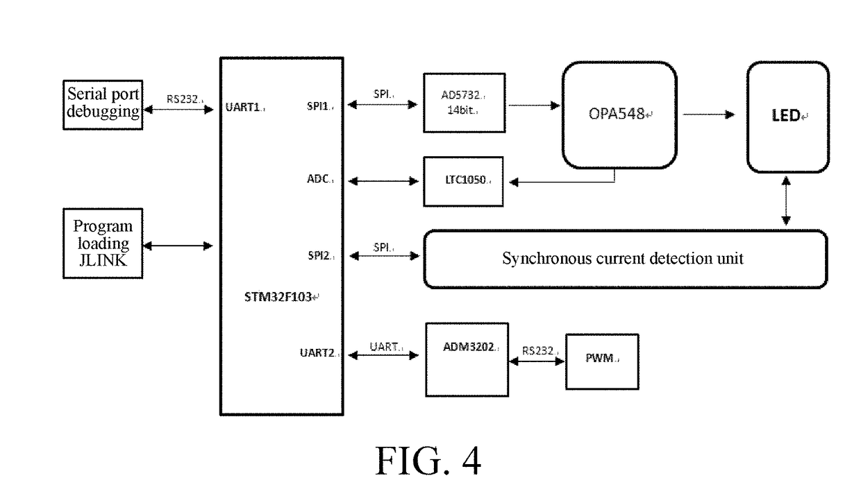
This patent aims to provide a system for detecting marine microscopic organisms using telecentric illumination and photographing. The system should create even and high-quality images, improving the detection of these organisms. Additionally, the patent seeks to provide an illumination drive with a large current and high reliability for detecting marine planktons.

Problems solved by technology

However, there are quite a lot of technical problems for technical means of researching microscopic organisms because sizes and dimensions of microscopic organisms are mostly at the micrometer scale, especially in a relatively turbid water body and in a water body of a sludge mixture.
When imaging microscopic organisms, a general illumination light source and a photographing camera have problems such as scattering, light interference, and non-uniform imaging illuminance, causing many adverse effects on observation of the microscopic organisms.
For example, scattering results in vague imaging and low contrast, coherent stripes are formed and an alternation of bright and dark areas of a part of an image surface is caused due to light interference, and non-uniform imaging illuminance affects overall observation of imaging.
A current-limiting resistor solution is applicable to an application scenario with low efficiency and has an extremely high requirement for efficiency.
Therefore, the method is not used for an illumination drive requiring high image acquisition accuracy.
The linear regulator is only applicable to a scenario of a low current or a scenario in which a forward voltage drop of an LED is slightly lower than a power supply voltage, but also has problems of low efficiency and a small input voltage range.
(1) A buck-boost function. When an input voltage or a voltage drop of an LED fluctuates, an output voltage is regulated, to satisfy a requirement that an output current is constant and ensure that the LED stably and reliably emits light.
(2) High power conversion efficiency. A circuit drive loss is lowered, energy consumption is reduced, a quantity of times of charging a storage battery is reduced, and a service life of a battery is prolonged.
(3) A brightness regulation function. When an exposure time of an imaging system needs to be regulated, a current may be regulated by using a PWM signal.
(4) There is a complete protection circuit. Various protection measures need to be taken to ensure reliable working of the protection circuit and the LED. The protection measures are, for example, low-voltage latching, over-voltage protection, overheat protection, and output open-circuit or short-circuit protection.
(5) A good heat dissipation function. Because of thermal properties of the LED, a temperature is one of important factors that affect stable working of the LED. When working at night, the LED is in a state of being lit up for a long time. Therefore, a good heat dissipation function is necessary, to ensure a service life and reliable working of the LED.

Method used


Image

  • Telecentric illumination and photographing system for detection of marine microscopic organisms
  • Telecentric illumination and photographing system for detection of marine microscopic organisms
  • Telecentric illumination and photographing system for detection of marine microscopic organisms

Examples


Embodiment Construction

[0052]Embodiments of the present application are described in detail below. It should be emphasized that the following descriptions are merely exemplary and are not intended to limit the scope and application of the present invention.

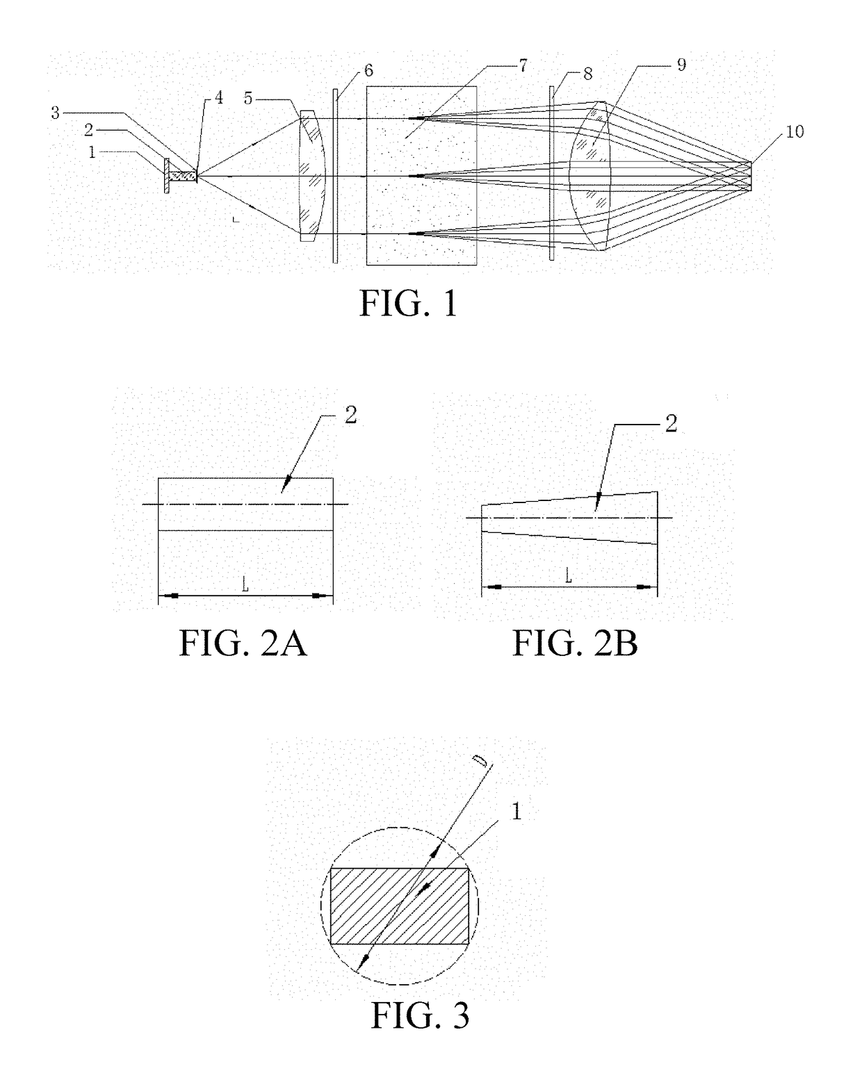
[0053]Referring to FIG. 1, in an embodiment, a telecentric illumination and photographing system for detection of marine microscopic organisms includes an optical path module and an illumination drive module. The optical path module includes an LED light source 1, a light homogenizing rod 2, a decoherence light homogenizing sheet 3, a diaphragm 4, a telecentric collimation camera 5, and a telecentric imaging camera 9. The LED light source 1 provides an illumination light source. The light homogenizing rod 2 mixes light beams emitted from the LED light source 1 to obtain uniform light intensity distribution. The decoherence light homogenizing sheet 3 performs secondary light homogenization on a light beam emitted from an end surface of the light homogeni...


PUM


Abstract

A telecentric illumination and photographing system for detection of marine microscopic organisms includes an optical path module and an illumination drive module, where the optical path module includes: an LED light source, a light homogenizing rod, a decoherence light homogenizing sheet, a diaphragm, a telecentric collimation camera, where a light beam emitted from the diaphragm is incident into a microscopic organism area with uniform illuminance after passing through the telecentric collimation camera; and a telecentric imaging camera, matching the telecentric collimation camera to receive an illumination beam passing through the microscopic organism area and output the illumination beam to an imaging unit, to obtain an imaging result of uniform illuminance. Further, the illumination drive module enables the LED light source to work in a stable state in which light emitting intensity is constant, thereby improving current output accuracy.

Description

CROSS REFERENCE TO RELATED APPLICATIONS[0001]This application is a continuation application of PCT / CN2016 / 077702, filed on Mar. 29, 2016. The contents of PCT / CN2016 / 077702 are all hereby incorporated by reference.BACKGROUNDTechnical Field[0002]The present application relates to an illumination and imaging technology, and in particular, to a telecentric illumination and photographing system for detection of marine microscopic organisms, providing illumination to detection of marine microscopic organisms.Related Arts[0003]With the development of scientific researches, it is found that data such as existence and growth of microscopic organisms in water system environments such as oceans, lakes, and rivers, ingredients of metabolins, and water-soluble gas ingredients all closely and accurately reflects a condition of a local environment and is closely linked with a living environment of people. However, there are quite a lot of technical problems for technical means of researching micro...

Claims


Application Information

Patent Timeline
Patent Type & Authority Applications(United States)
IPC IPC(8): H04N5/225F21V8/00F21V9/14H05B33/08F21K9/61H05B44/00
CPCH04N5/2256H05B33/0845F21K9/61F21V9/14G02B6/0001F21Y2115/10H05B45/10H04N23/56H04N23/74G02B13/22H05B45/12
Inventor CHENG, XUEMINBI, HONGSHENGHE, YONGHONGCAI, ZHONGHUALIN, JIAYONG
Owner SHENZHEN GRADUATE SCHOOL TSINGHUA UNIV
Learn More