Air conditioning system

a technology of air conditioner and air conditioner, which is applied in the direction of ventilation systems, lighting and heating apparatus, heating types, etc., can solve the problems of inability to reliably perform ventilation when refrigerant leakage occurs, and the accident caused by refrigerant leakage from the air conditioner cannot be eliminated, so as to achieve the effect of suppressing costs

Active Publication Date: 2018-02-15
DAIKIN IND LTD
View PDF3 Cites 32 Cited by
  • Summary
  • Abstract
  • Description
  • Claims
  • Application Information

AI Technical Summary

Benefits of technology

[0033]Because of this, it becomes possible to construct a communication network using an existing communication line of the air conditioner (e.g., a communication

Problems solved by technology

However, when the air conditioner and the ventilation unit are selected and installed independently of each other, sometimes the installation work is performed by different contractors, and a case is also conceivable where the connection of the electrical communication system between devices including the refrigerant leak sensor is not done reliably.
In this case, ventilation when refrigerant leakage has occurred does not be reliably performed.
That is, in a c

Method used


Image

  • Air conditioning system
  • Air conditioning system
  • Air conditioning system

Examples


example modification b

(8-2) Example Modification B

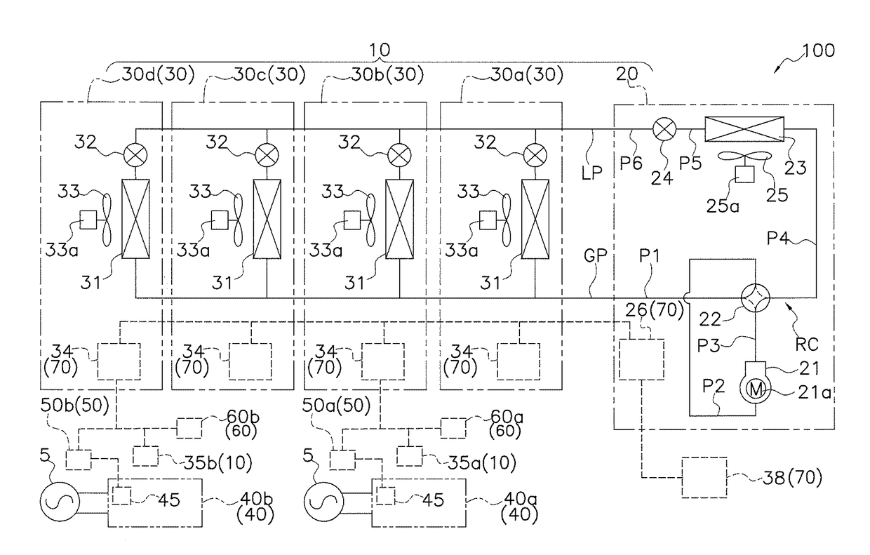
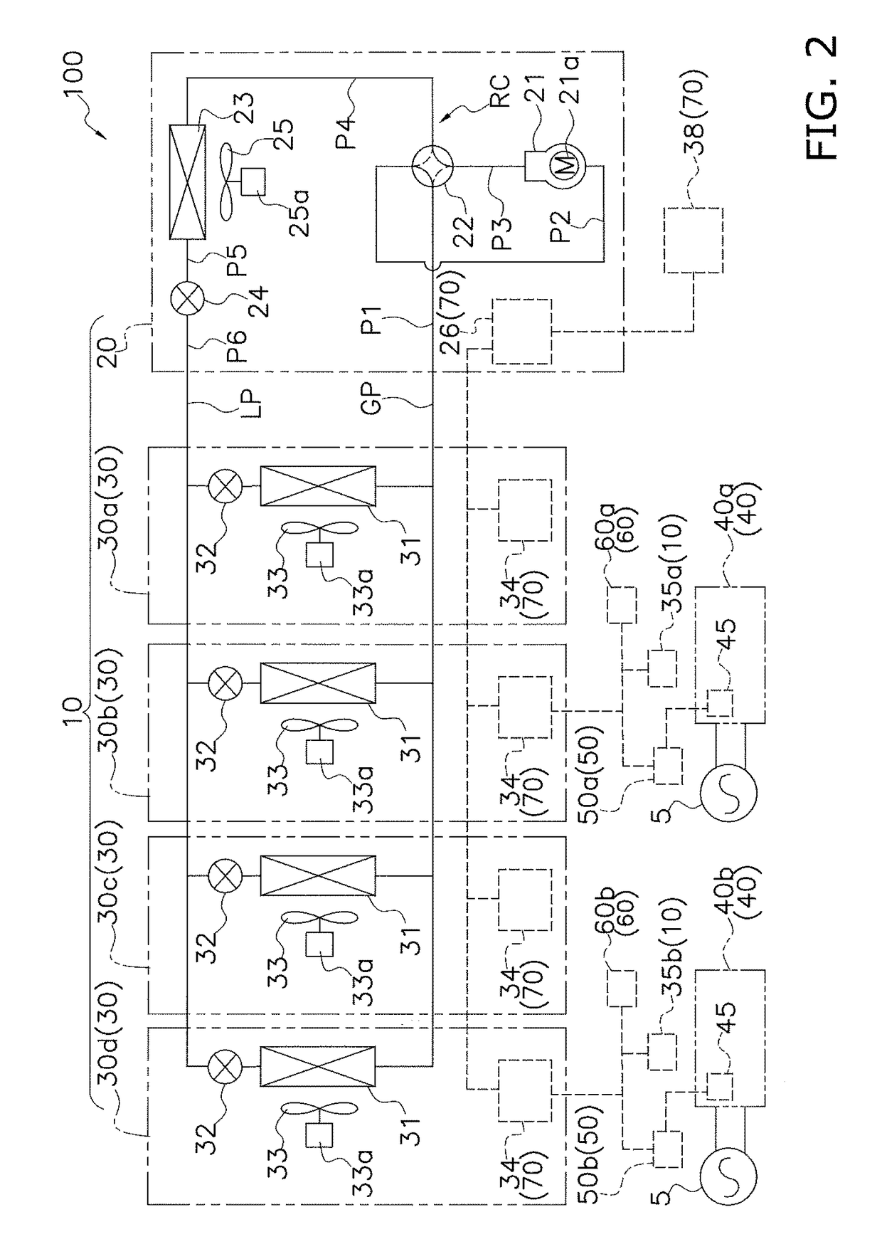
[0200]In the embodiment, the ventilation unit 40 had two ventilation fans (the supply air fan 43 and the exhaust air fan 44). However, it is not invariably necessary for the ventilation unit 40 to have two ventilation fans. That is, the ventilation unit 40 may also have just one ventilation fan. In this case, it suffices to do away with one of the air flow paths (the supply air flow path 41a and the exhaust air flow path 41b) inside the body frame 41.

[0201]Furthermore, the ventilation unit 40 included the heat exchanger 42, but the heat exchanger 42 is not invariably necessary and can be appropriately omitted.

[0202]Furthermore, sirocco fans were employed as the ventilation fans, but other fans such as propeller fans, for example, may also be employed as the ventilation fans.

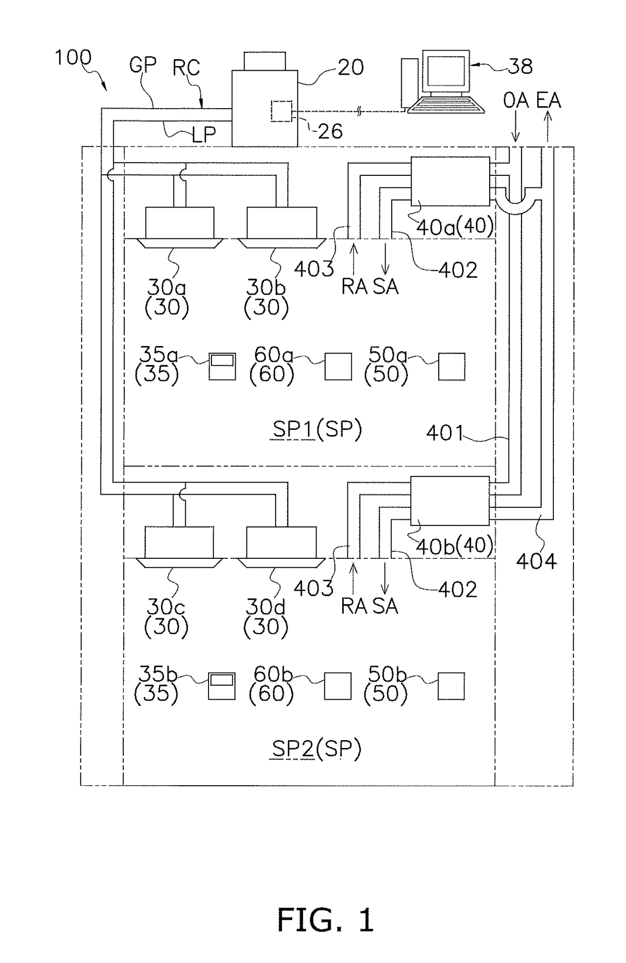
[0203]Furthermore, it is not invariably necessary for the ventilation unit 40 to be installed in the space behind the ceiling of the target space SP, and the installation of the ventil...

example modification c

(8-3) Example Modification C

[0204]In the embodiment, the ventilation unit 40 had the fan drive control component 45 including an inverter. However, in the ventilation unit 40, it is not invariably necessary for the fan drive control component 45 to include an inverter. That is, a unit incapable of adjusting the rotational speed of the ventilation fan may also be employed as the ventilation unit 40. In this case, the rotational speed control signal becomes a signal that switches between powering on / off the ventilation unit 40.

example modification d

(8-4) Example Modification D

[0205]The air conditioning system 100 of the embodiment may also be configured like an air conditioning system 200 shown in FIG. 9. The air conditioning system 200 will be described below. It should be noted that description regarding parts common to the air conditioning system 100 will be omitted.

[0206]In the air conditioning system 200, ventilation units 80 (80a and 80b) are disposed instead of the ventilation units 40 (40a and 40b), and adapter units 90 (90a and 90b) are disposed instead of the adapter units 50 (50a and 50b).

[0207]Each ventilation unit 80 has one ventilation fan 81 and a ventilation fan motor 81a that corresponds to a drive component of the ventilation fan 81. Furthermore, the ventilation fan 81 has a drive circuit 82 (a fan drive control component) for the ventilation fan motor 81a.

[0208]The adapter units 90 are disposed between the commercial power supplies 5 and the ventilation units 80, and are connected in series to the commercia...


PUM


Abstract

An air conditioning system has an air conditioner, which includes an outdoor unit and an indoor unit that configure a refrigerant circuit, and a controller, which controls the running of the air conditioner. The controller does not allow operation of the air conditioner to start in a case where a signal from a ventilation unit that includes a ventilation fan for ventilation and ventilates a target space or a refrigerant leak sensor that detects refrigerant leakage in the target space is not input to the controller. Because of this, even in a configuration where an air conditioner and a ventilation unit are installed independently of each other, operation of the air conditioner can be performed in a state in which there is reliably established a countermeasure such as the ventilation unit being operated when the refrigerant has leaked, and safety and security with respect to refrigerant leakage are reliably ensured.

Description

TECHNICAL FIELD[0001]The present invention relates to an air conditioning system including an air conditioner that cools or heats a target space by causing refrigerant to circulate in a refrigerant circuit during operation.BACKGROUND ART[0002]Conventionally, a configuration has been proposed where, as in Patent Document 1 (JP-A No. 2001-74283), an indoor unit of an air conditioner having a refrigerant circuit through which a combustible refrigerant circulates, a ventilation fan (a ventilation unit), and a sensor (a refrigerant leak sensor) that detects combustible gas are installed in a room (a target space), and when leakage of the combustible refrigerant has been detected, the ventilation unit is operated to thereby discharge the combustible refrigerant from the target space.SUMMARY OF INVENTION[0003]Here, in a case of configuring an air conditioning system to cool, heat, and ventilate a target space by installing an air conditioner and a ventilation unit in a building such as a m...

Claims


Application Information

Patent Timeline
IPC IPC(8): F24F11/00
CPCF24F11/008F24F11/006F24F11/0079F24F2011/0084F24F2011/0071F24F2011/0061F24F7/007F24F2221/32F25B49/02F24F11/36F24F11/58F24F11/62F24F11/63F24F11/77F24F11/83F24F11/89Y02B30/70F24F11/0001F24F11/30
Inventor YAJIMA, RYUUZABUROUIURA, TSUTOMUAISAKA, YASUYUKISUNAHATA, TAIKINOBURYUU, DAISUKE
Owner DAIKIN IND LTD
Why Eureka
Try Eureka