Eureka AIR delivers breakthrough ideas for toughest innovation challenges, trusted by R&D personnel around the world.

Current conductor structure with frequency-dependent resistance

Inactive Publication Date: 2018-02-15
ABB (SCHWEIZ) AG
View PDF4 Cites 0 Cited by
  • Summary
  • Abstract
  • Description
  • Claims
  • Application Information

AI Technical Summary

Benefits of technology

The present invention provides a current conductor structure that can be used in power transfer and filtering applications with minimal loss of power. The structure consists of layers of insulating material with thin strips of electrically conducting material running between them. Different materials can be used for each conductor to achieve the desired resistivity and limit frequency. The current conductor structure can be integrated into existing power transfer loops or used for selective filtering.

Problems solved by technology

The electromagnetic energy in these high-frequency currents and voltages may be small in comparison to the rated power of the converter, but the currents and voltages may still be harmful to the electrical environment or to the converter itself.
In a frequency converter, for example, oscillating high-frequency currents may cause additional losses in components of the converter, and high-frequency voltages may induce additional stress to the components and age them prematurely, especially in commutation circuits of switching components of the frequency converter.
The switching components of a frequency converter may have the highest impact on power losses of the converter.
Thus, slowing them down may induce high additional power losses thereby having a significant negative effect on a total efficiency of the converter.
Further, even with a dedicated gate control of active switches such as IGBTs, frequency content of the additional losses may not be selectively controllable.
Furthermore, the rate of change of the voltage at a turn-off may be directly set by the design and operating point of the IGBT device, and thus, may not be controllable.
These components may increase the cost and size of the converter.
Further, in the case of a serial filtering, for example, both an inductance and a resistance may have negative effects to the efficiency of the power flow at fundamental frequency because of voltage drops and losses in conductors and cores of magnetic components.
Placing resistors to the commutation circuits may also increase the inductance of the circuits which, in turn, may induce higher overvoltage spikes that may stress components inside, as well as outside the converter.

Method used


Image

  • Current conductor structure with frequency-dependent resistance
  • Current conductor structure with frequency-dependent resistance
  • Current conductor structure with frequency-dependent resistance

Examples


Embodiment Construction

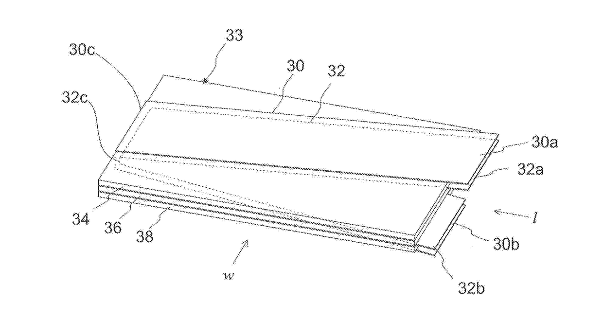
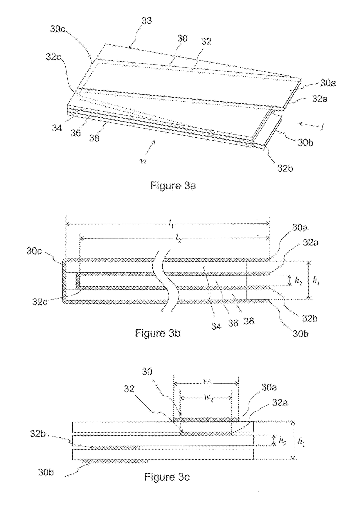
[0017]The present disclosure describes a current conductor structure with a frequency-dependent resistance. The current conductor structure may be in the form of a bus bar in a main circuit of a power electronics converter, for example. The power electronic converter, may be a frequency converter, for example.

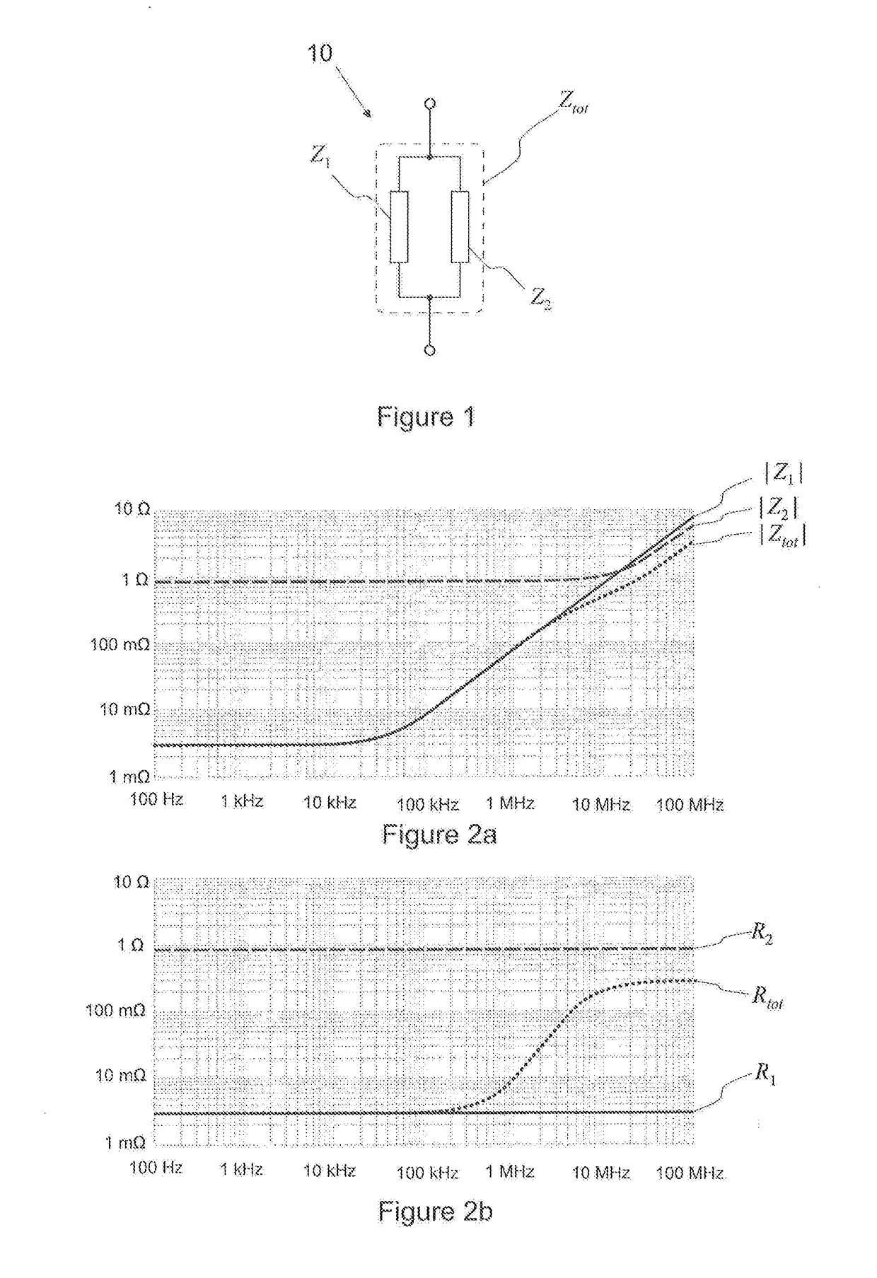
[0018]The current conductor structure may comprise at least a first current path and a second current path connected in parallel. The first and second current path may be configured such that the second current path has a higher resistance and a lower inductance than the first current path. As a result, the resistance component of a total impedance of the current conductor structure is larger than the resistance component of the impedance of the first current path at frequencies above a set frequency limit. A current through a resistance dissipates power into heat. Therefore, the current conductor structure selectively dampens currents at frequencies above the set frequency lim...


PUM


Abstract

A current conductor structure with a frequency-dependent resistance. The current conductor structure comprises a first current conductor and a second current conductor connected in parallel. The first and second current conductor are configured such that the second current conductor has a higher resistance and a lower inductance than the first conductor so that, above a set frequency limit, the resistance component of a total impedance of the current conductor structure is larger than the resistance component of the impedance of the first conductor current.

Description

FIELD[0001]The present disclosure relates to high-frequency electrical emissions and particularly to damping of such emissions in a power converter.BACKGROUND[0002]Rated powers of power electronics converters may range from several hundreds of watts to megawatts, for example. This power may be transmitted at frequencies that are in the range of few Hertz to hundreds of Hertz. Power electronics converters may use hard-switched semiconductors for switching of currents and voltages. Because of this, the semiconductors may be a source of a wide bandwidth of voltages and currents at frequencies other that those used for transmitting the power. The electromagnetic energy in these high-frequency currents and voltages may be small in comparison to the rated power of the converter, but the currents and voltages may still be harmful to the electrical environment or to the converter itself. In a frequency converter, for example, oscillating high-frequency currents may cause additional losses i...

Claims


Application Information

Patent Timeline
IPC IPC(8): H01F27/28H01F41/063
CPCH01F41/063H01F27/2847H01B5/14H02M1/44H03H7/06H01F2027/2861
Inventor MASTI, MIKAKINNUNEN, HENRILAITINEN, MATTI
Owner ABB (SCHWEIZ) AG
Why Eureka
Eureka Blog
Learn More