Soundproof structure and soundproof structure manufacturing method

a soundproof structure and manufacturing method technology, applied in the direction of instruments, buildings, building components, etc., can solve the problems of large and heavy soundproof structures, difficult to shield low frequencies, and soundproof structures with large and heavy weight, and achieve excellent manufacturing suitability and high robustness.

Active Publication Date: 2018-02-22
FUJIFILM CORP
View PDF10 Cites 24 Cited by
  • Summary
  • Abstract
  • Description
  • Claims
  • Application Information

AI Technical Summary

Benefits of technology

[0050]According to the present invention, it is possible to provide a soundproof structure which is light and thin, in which sound insulation characteristics such as a shielding frequency and a shielding size do not depend on the shape, which has high robustness as a sound insulation material and is stable, which is suitable for equipment, automobiles, and household applications, and which is excellent in manufacturing suitability.
[0051]In particular, according to the present invention, by using two or more types of different soundproof cells having different hardnesses of shielding structures each of which is configured to include a frame and a film, specifically, having different effective hardnesses determined by a film material (physical properties of a film, such as a Young's modulus and a density), film thickness, film size (frame size), film tension, and the like, it is possible to shield, that is, reflect and / or absorb an arbitrary desired frequency component very strongly.
[0052]That is, according to the present invention, it is possible to realize strong sound insulation simply by bonding two structures configured to include a frame and a film and having different “hardnesses”, for example, bonding two types of films having different thicknesses and / or two types of films having different types (physical properties) to the same frame or by bonding the same film to frames having different sizes.

Problems solved by technology

Incidentally, most of the conventional soundproof structures are disadvantageous in that the soundproof structures are large and heavy due to sound insulation by the mass of the structures and that it is difficult to shield low frequencies.
However, there has been a problem that the range of selection of a sound absorbing material is narrow and accordingly it is difficult to achieve the high sound absorption effect in a low frequency region.
For this reason, a place where installation takes place or the size has been greatly limited.
Since the sound absorbing material of such a sound absorber completely blocks the through-hole of the frame body, the sound absorbing material does not allow wind or heat to pass therethrough and accordingly heat tends to accumulate on the inside.
For this reason, there is a problem that this is not suitable for the sound insulation of equipment and automobiles, which is disclosed in JP4832245B in particular.

Method used


Image

  • Soundproof structure and soundproof structure manufacturing method
  • Soundproof structure and soundproof structure manufacturing method
  • Soundproof structure and soundproof structure manufacturing method

Examples


examples

[0304]The soundproof structure of the present invention will be specifically described by way of examples.

[0305]Before performing an experiment to manufacture an example of the present invention and measure the acoustic characteristic, the design of the soundproof structure by simulation is shown.

[0306]Since the system of the soundproof structure is an interaction system of film vibration and sound waves in air, analysis was performed using coupled analysis of sound and vibration. Specifically, designing was performed using an acoustic module of COMSOL ver 5.0 that is analysis software of the finite element method. First, a first resonance frequency was calculated by natural vibration analysis. Then, by performing acoustic structure coupled analysis based on frequency sweep in the periodic structure boundary, transmission loss at each frequency with respect to the sound wave incident from the front was calculated. Based on this design, the shape or the material of the sample was det...

example s1

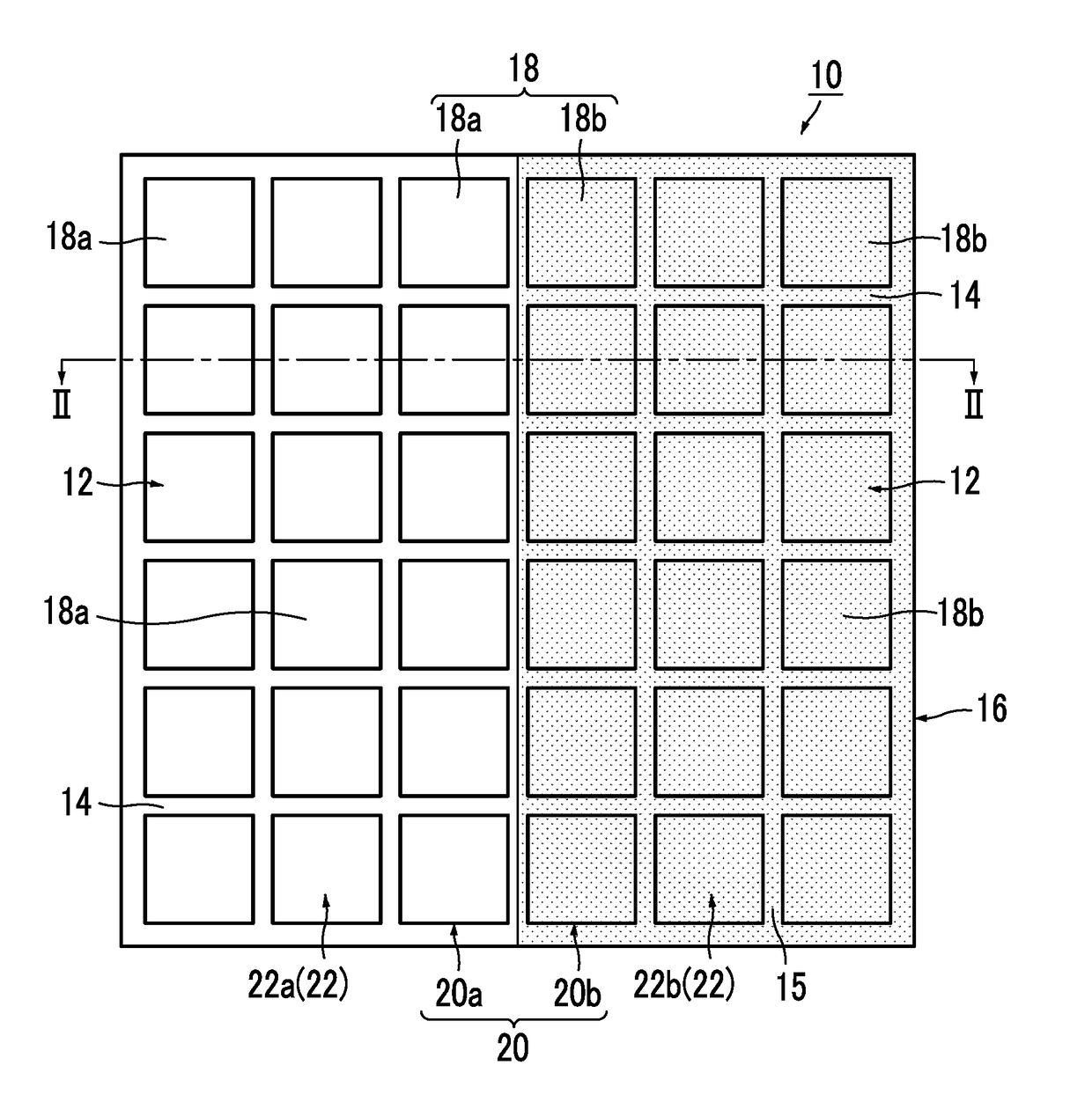
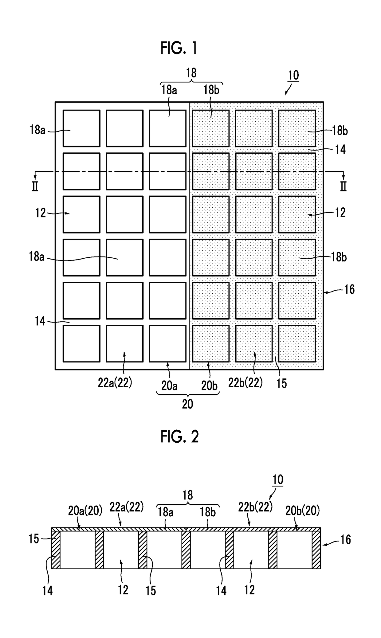
[0309]First, regarding the simulation of the soundproof structure 10 of the present invention in which two types of PET films having different thicknesses are fixed to the 20-mm frame 14 as the film 18, transmission loss in a case where the PET film of one film 18a has a thickness of 100 μm and the PET film of the other film 18b has a thickness of 125 μm, 150 μm, 175 μm, 200 μm, 225 μm, and 250 μm is shown in FIG. 6. The frame 14 was a square having a size of 20 mm, the first resonance frequency of the soundproof cell 22a of the PET film (100 μm) of one film 18a was 800 Hz, the first resonance frequency of the soundproof cell 22b of the PET film having a different thickness of the other film 18b was on the higher frequency side, and a maximum value of the transmission loss appeared at the frequency therebetween. The frequency indicating the maximum value is the shielding peak frequency.

[0310]As is apparent from FIG. 6, as described above, in the soundproof structure 10 of the presen...

example s2

[0311]Next, in the soundproof structure 10 of the present invention, from the viewpoint of shielding low frequencies, the frame 14 was a square having a size of 25 mm, the film thickness of the PET film of one film 18a was set to 50 μm, and the size of the frame 14 was set to 25 mm, so that the first resonance frequency became a low frequency. Simulation was performed by combining the 25-mm square frame 14 and the PET film having a film thickness of 80 μm, 100 μm, and 120 μm of the other film 18b, and the frequency dependence of transmission loss was calculated. The result is shown in FIG. 7. It was found that the maximum value of transmission loss also appeared on the low frequency side near the frequencies of 300 Hz to 500 Hz.

[0312]As is apparent from FIG. 7, as described above, the soundproof structure 10 of the present invention shows the same tendency as in FIG. 6 even if the PET film is made thinner as a whole.


PUM


Abstract

A soundproof structure has a plurality of soundproof cells arranged in a two-dimensional manner. Each of the plurality of soundproof cells includes a frame formed of a frame member forming an opening and a film fixed to the frame. Two or more types of soundproof cells having different first resonance frequencies are present in the plurality of soundproof cells. A shielding peak frequency at which transmission loss is maximized is present within a range equal to or higher than a lowest frequency among first resonance frequencies of the soundproof cells and equal to or lower than a highest frequency among the first resonance frequencies of the soundproof cells.

Description

CROSS-REFERENCE TO RELATED APPLICATIONS[0001]This application is a Continuation of PCT International Application No. PCT / JP2016 / 68392 filed on Jun. 21, 2016, which claims priority under 35 U.S.C. §119(a) to Japanese Patent Application No. 2015-124639 filed on Jun. 22, 2015 and Japanese Patent Application No. 2016-090881 filed on Apr. 28, 2016. Each of the above applications is hereby expressly incorporated by reference, in its entirety, into the present application.BACKGROUND OF THE INVENTION1. Field of the Invention[0002]The present invention relates to a soundproof structure, and more particularly to a soundproof structure in which two or more types of soundproof cells having different effective hardnesses, each of which has a frame and a film fixed to the frame, are arranged in a two-dimensional manner in order to strongly shield the sound of a target frequency selectively.2. Description of the Related Art[0003]In the case of a general sound insulation material, as the mass incre...

Claims


Application Information

Patent Timeline
Patent Type & Authority Applications(United States)
IPC IPC(8): E04B1/84
CPCE04B1/8404E04B1/8409E04B2001/8476E04B1/86G10K11/172E04B2001/848
Inventor HAKUTA, SHINYAYAMAZOE, SHOGOKASAMATSU, TADASHINAYA, MASAYUKI
Owner FUJIFILM CORP
Why Eureka
Try Eureka