Liquid crystal display device and method for driving same

a technology of liquid crystal display and driving method, which is applied in the direction of instruments, static indicating devices, etc., can solve the problems of low light utilization efficiency, insufficient image quality, and difficulty in implementing color filter systems, so as to simplify calculation circuit, and suppress color shift occurrence

Active Publication Date: 2018-02-22
SHARP KK
View PDF6 Cites 5 Cited by
  • Summary
  • Abstract
  • Description
  • Claims
  • Application Information

AI Technical Summary

Benefits of technology

[0066]According to the first aspect of the present invention, in a liquid crystal display device employing the field sequential system, correction processing that changes the saturation without changing the hue is performed on the input pixel data so that the color after correction is a color that can be displayable by the field sequential system. Since the impression received by a person with respect to the displayed image changes more significantly when the hue changes than when the lightness or the saturation changes, occurrence of color shift is suppressed by performing color correction without changing the hue in this way. From the above, a liquid crystal display device employing the field sequential system and capable of suppressing occurrence of color shift is realized.
[0067]According to the second aspect of the present invention, before the color correction processing is performed, processing of allocating data of a plurality of colors to fields is performed in accordance with display order of colors in the frame. Then, in the correction calculation unit, calculation processing is performed based on order data obtained by this allocation. That is, in the correction calculation unit, calculation processing is performed without considering colors in the frame. Since such a configuration is adopted, it is possible to simplify the calculation circuit in the correction calculation unit. Thus, an effect of cost reduction due to reduction in circuit scale can be obtained.
[0068]According to the third aspect of the present invention, regarding data of a color that can not be displayed, correction is performed so that the hue does not change and the variation amount for the saturation is as small as possible. Accordingly, occurrence of large color shift is suppressed when a color image is displayed.
[0069]According to the fourth aspect of the present invention, similarly to the third aspect of the present invention, occurrence of large color shift is suppressed when a color image is displayed.
[0070]According to the fifth aspect of the present invention, the same effect as in the third aspect of the present invention can be obtained with a relatively small memory capacity.
[0071]According to the sixth aspect of the present invention, correction is performed on the input pixel data so that data of all colors are data of colors that can be displayed and gradation display can be performed also regarding high saturation colors. Thus, a liquid crystal display device employing the field sequential system, capable of suppressing occurrence of color shift, and capable of performing gradation display also regarding high saturation colors is realized.

Problems solved by technology

Hence a liquid crystal display device employing a color filter system has a problem of low efficiency in light utilization.
Further, in the liquid crystal display device, a sufficient image quality may not be obtained, for example at the time of displaying a moving image, due to a low response speed of the liquid crystal.

Method used


Image

  • Liquid crystal display device and method for driving same
  • Liquid crystal display device and method for driving same
  • Liquid crystal display device and method for driving same

Examples


first embodiment

1. First Embodiment

[0140]

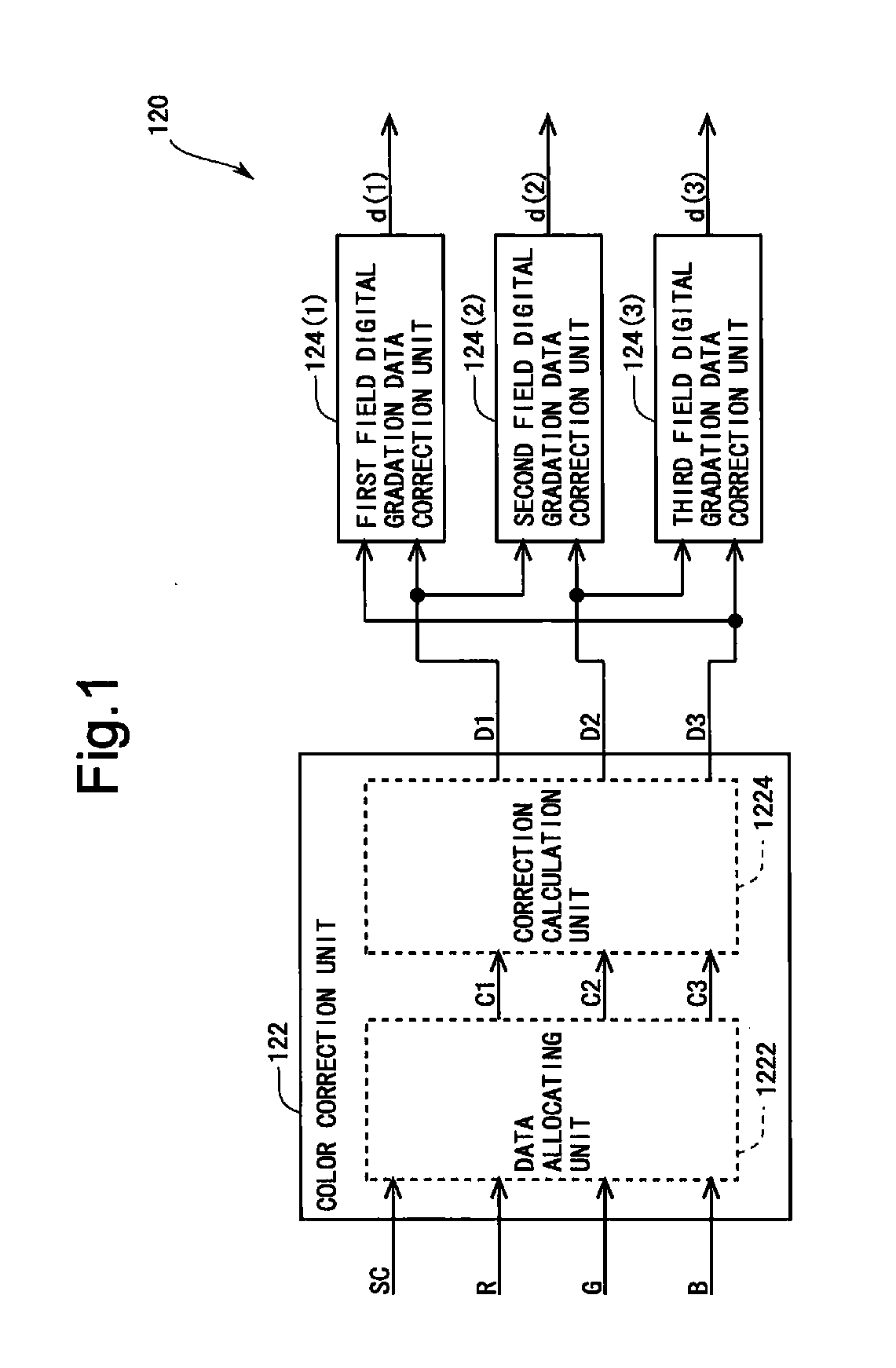
[0141]FIG. 9 is a block diagram showing an overall configuration of the liquid crystal display device according to the first embodiment of the present invention. The liquid crystal display device includes a preprocessing unit 100, a timing controller 200, a gate driver 310, a source driver 320, an LED driver 330, a liquid crystal panel 400, and a backlight 490. It should be noted that the gate driver 310 or the source driver 320 or both thereof may be provided within the liquid crystal panel 400. The liquid crystal panel 400 includes a display unit 410 for displaying an image. The preprocessing unit 100 includes a signal separation circuit 110, a data correction circuit 120, a first field memory 130(1), a second field memory 130(2), and a third field memory 130(3). In the present embodiment, LEDs (light emitting diodes) are adopted as the light sources of the backlight 490. Specifically, the backlight 490 is constituted by red LEDs, green LEDs, and blue LEDs...

second embodiment

2. Second Embodiment

[0210]

[0211]The overall configuration, the configuration of the data correction circuit, and the configuration of one frame period are the same as those in the first embodiment, and therefore the description thereof is omitted (see FIG. 9, FIG. 1, and FIG. 10). The contents of the color correction processing are different between the present embodiment and the first embodiment. Therefore, hereinafter, the color correction processing in the present embodiment will be described.

[0212]

[0213]FIG. 25 is a flowchart showing a detailed procedure of the color correction processing performed by the correction calculation unit 1224 in the present embodiment. In step S210 and step S220, the same processings as step S110 and step S120 in the first embodiment (see FIG. 12) are performed.

[0214]Meanwhile, in the first embodiment, in the displayable range table, the maximum distances La are held so as to correspond to the combination of m and cos θ (see FIG. 13 and FIG. 16). If ...

third embodiment

3. Third Embodiment

[0219]

[0220]The overall configuration, the configuration of the data correction circuit, and the configuration of one frame period are the same as those in the first embodiment, and therefore the description thereof is omitted (see FIG. 9, FIG. 1, and FIG. 10). The contents of the color correction processing are different between the present embodiment and the first embodiment. Therefore, hereinafter, the color correction processing in the present embodiment will be described.

[0221]

[0222]In the first embodiment, when the value of L is larger than the value of La, the color corresponding to the point D located at the distance La from the point P toward the point C in the display order color space is set as the order color after correction (see FIG. 13) regardless of the magnitude of the value of L. In this case, regarding each combination of m and cos θ, the order colors where the distance from the pseudo achromatic axis 52 is larger than or equal to La (namely, th...


PUM


Abstract

A liquid crystal display device employing a field sequential system includes: a color correction unit (122) configured to perform a color correction processing that changes a saturation of input gradation data representing a color of a pixel without changing a hue thereof and configured to output pixel data obtained by the color correction processing as digital gradation data (D1 to D3) which are data corresponding to each field; and a digital gradation data correction unit configured to perform correction that enhances a temporal change of data values of digital gradation data (D1 to D3) outputted from the color correction unit (122). The color correction unit (122) performs the color correction processing on the input gradation data such that a color based on pixel data obtained by the color correction processing is a color that can be displayable in the liquid crystal panel by the field sequential system.

Description

TECHNICAL FIELD[0001]The present invention relates to a liquid crystal display device and a driving method thereof, and more specifically to a technique of suppressing occurrence of color shift in a liquid crystal display device employing a field sequential system.BACKGROUND ART[0002]In general, in a liquid crystal display device that performs color display, one pixel is divided into three sub pixels of a red pixel, a green pixel, and a blue pixel, the red pixel being provided with a color filter that transmits red light, the green pixel being provided with a color filter that transmits green light, the blue pixel being provided with a color filter that transmits blue light. While color display is possible by use of the color filters provided in the three sub pixels, about two-thirds of backlight light applied to a liquid crystal panel is absorbed in the color filters. Hence a liquid crystal display device employing a color filter system has a problem of low efficiency in light util...

Claims


Application Information

Patent Timeline
Patent Type & Authority Applications(United States)
IPC IPC(8): G09G3/34G09G3/36
CPCG09G3/3413G09G3/3648G09G3/3607G09G2320/062G09G2300/0452G09G2310/08G09G2320/0242G09G3/3688G09G2310/0235G09G2320/0252G09G2320/028G09G2320/10G09G2340/00G09G2360/16
Inventor MIYATA, HIDEKAZUKOBAYASHI, MASAMITSU
Owner SHARP KK
Why Eureka
Try Eureka