Method of producing a magnetic structure

a magnetic structure and method technology, applied in the field of method of producing a magnetic structure, can solve the problems of reducing the degree of miniaturization that is desired, reducing the inventive aspect ratio, and reducing the degree of miniaturization achieved by conventional methods, etc., to achieve the effect of high inventive aspect ratio, high magnetic flux density, and increasing magnetic flux density

Active Publication Date: 2018-02-22
FRAUNHOFER GESELLSCHAFT ZUR FOERDERUNG DER ANGEWANDTEN FORSCHUNG EV
View PDF7 Cites 4 Cited by
  • Summary
  • Abstract
  • Description
  • Claims
  • Application Information

AI Technical Summary

Benefits of technology

[0019]In addition, it is conceivable for the cavities to be introduced into the substrate such that each cavity has a lateral extension of 250 μm or less or of 100 μm or less or of 50 μm or less or of 25 μm or less. I.e., if the cavity has a lateral extension of 10 μm at an aspect ratio of 6:1, the cavity will have a depth of 60 μm. The indicated lateral extensions in combination with the inventive aspect ratios thus result in particularly advantageous implementations of magnetic porous structures having magnetic flux densities which are clearly higher as compared to the conventional technology.
[0020]In accordance with one embodiment of the inventive method, the substrate may have an additional coating applied to it which extends across the cavities filled with the magnetic particles so as to seal the cavities. Said additional coating may be applied onto the outer side of the substrate, specifically onto that outer side of the substrate where there are the openings of the cavities. Said additional coating may be applied onto the magnetic porous structures and onto the substrate, e.g., by means of sputtering, electrodeposition or by means of PECVD (Plasma-Enhanced Chemical Vapor Deposition). Said additional coating may provide reliable protection from corrosion, for example if the magnetic porous structures are sealed on all sides, and advantageously hermetically, by means of the additional coating. Moreover, with the additional coating one may achieve considerable improvement of the magnetic properties of the magnetic porous structures when the magnetic flux of the magnetic porous structures may be closed by applying a, e.g., soft magnetic layer, e.g. Fe or NiFe. The coating may comprise one or more layers, e.g. a dielectric layer and a soft magnetic layer.
[0024]In accordance with embodiments of the invention, the etch stop layer may be arranged between the substrate and an SOI layer, the SOI layer having a layer thickness of between 1 μm and 100 μm, or a layer thickness of between 10 μm and 100 μm, or a layer thickness of between 50 μm and 100 μm. The distance between the deepest point of the cavity and that outer side of the substrate which is closest in the direction of depth might therefore be reduced to few micrometers. Layer thicknesses of between 1 μm and 100 μm are useful for achieving sufficient mechanical stability.
[0028]In this context it would be feasible for the base substrate to comprise silicon and for the covering substrate to comprise plastic. Plastic may be processed in a simple manner and is considerably cheaper than silicon.

Problems solved by technology

Often, the degree of miniaturization that is desired is difficult to achieve by means of conventional techniques since there are limits to mechanical processing of permanent magnets, inter alia due to the brittleness of the materials (e.g. NdFeB).
Said magnetic position detection is obviously limited mainly by the magnetic measuring bar.
However, only few hard magnetic materials, which additionally are comparatively weak, can be electrodeposited, such as CoPt, FePt or CoNiMnP, for example.
Also, layer thicknesses of more than 50 μm are very difficult to implement since any follow-up processes performed at elevated temperatures may easily result in stress-induced delamination of the galvanic structures.
However, sputtered layers are mostly limited to thicknesses of few micrometers.
Disadvantageous as compared to structures produced by electrodeposition are the high deposition temperatures as well as the fact that the sputtered layer subsequently needs to be structured (patterned).

Method used


Image

  • Method of producing a magnetic structure
  • Method of producing a magnetic structure
  • Method of producing a magnetic structure

Examples


Embodiment Construction

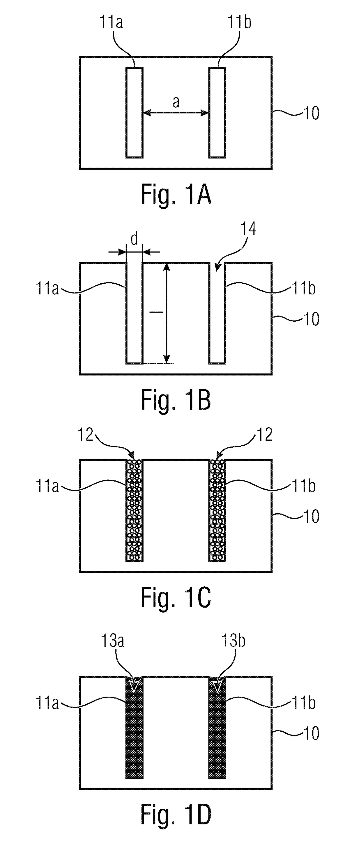
[0053]FIGS. 1A to 1D show graphic pictures for illustrating an inventive method.

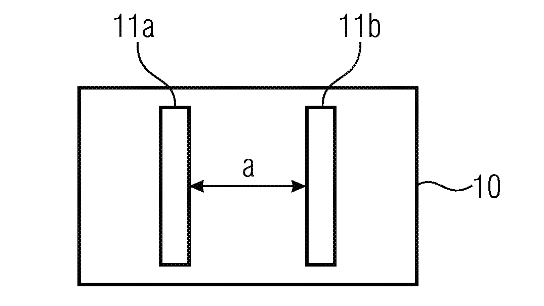
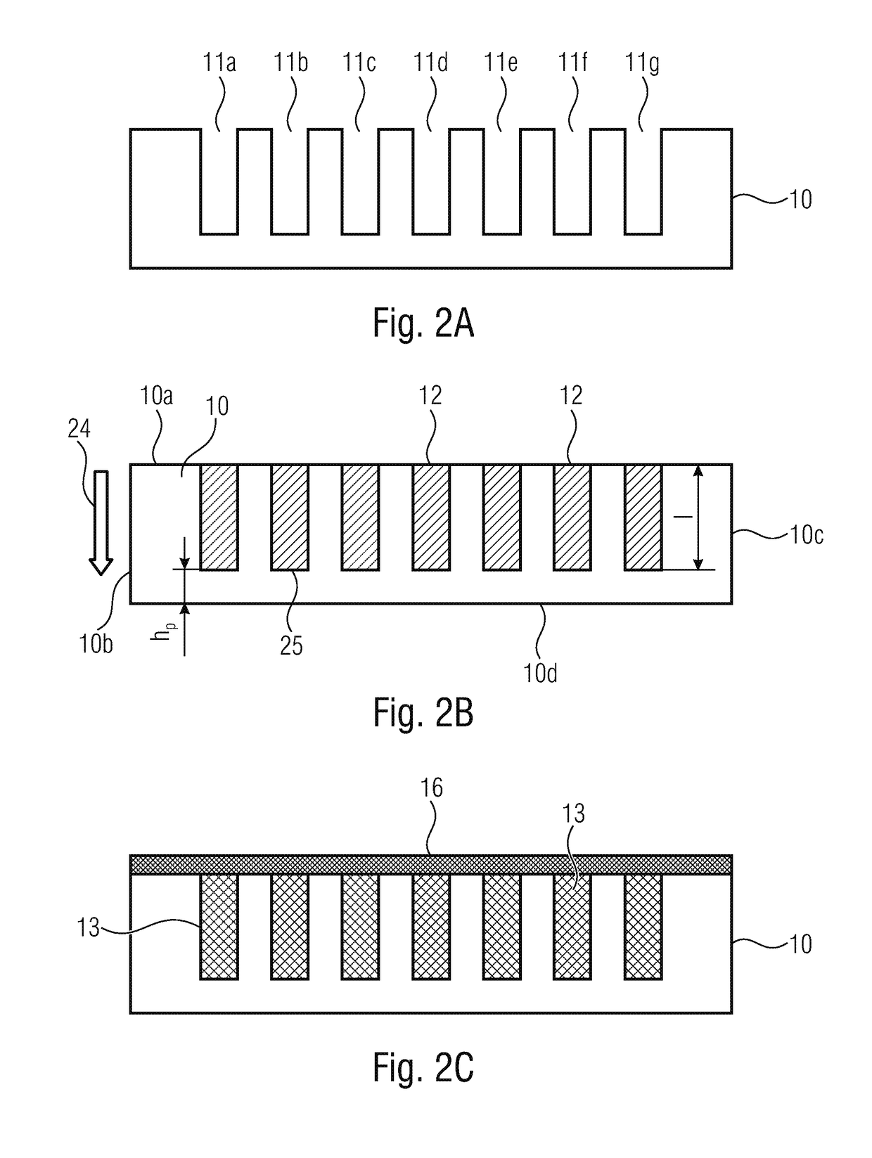
[0054]FIG. 1A shows a top view of a substrate 10 comprising two mutually spaced-apart cavities 11a, 11b. The cavities 11a, 11b are introduced into the substrate 10 by means of suitable methods. The left-hand cavity 11a is spaced apart by a measure a from the right-hand cavity 11b. Said measure a will also be referred to as pitch when illustrating the following embodiments.

[0055]FIG. 1B shows a lateral view of the substrate 10. As is shown in the example of the left-hand cavity 11a, the cavity 11a comprises a depth, or depth of penetration, of the length l as well as a lateral extension of the width d. The ratio of the length l to the width d is also referred to as an aspect ratio l / d.

[0056]In accordance with the invention, the cavity 11a has a depth / of at least 50 μm. In accordance with some embodiments, the cavity 11a may also have an aspect ratio l / d of at least 4:1 or of at least 6:1 or even of at lea...


PUM

PropertyMeasurementUnit
depthaaaaaaaaaa
residual thicknessaaaaaaaaaa
thicknessaaaaaaaaaa

Abstract

A device and to a method of producing a device, wherein the method includes, inter alia, providing a substrate and generating at least two mutually spaced-apart cavities within the substrate. In accordance with the invention, each cavity has a depth of at least 50 μm. The cavities are filled up with magnetic particles, wherein the magnetic particles enter into contact with one another at points of contact, and wherein cavities are formed between the points of contact. At least some of the magnetic particles are connected to one another at their points of contact, specifically by coating the magnetic particles, wherein the cavities are at least partly penetrated by the layer produced in the coating process, so that the connected magnetic particles form a magnetic porous structure.

Description

CROSS-REFERENCE TO RELATED APPLICATIONS[0001]This application claims priority from German Patent Application No. 10 2016 215 616.0, which was filed on Aug. 19, 2016, and is incorporated herein in its entirety by reference.[0002]The invention relates to a method of producing a magnetic structure in accordance with the features of claim 1, to a device having a magnetic structure in accordance with the features of claim 14, and to a system comprising such a device having a magnetic structure and a magnetic sensor in accordance with the features of claim 21.BACKGROUND OF THE INVENTION[0003]For many technical devices, three-dimensional arrangements of permanent magnets for generating specific field patterns are indispensable for many technical devices. Often, the degree of miniaturization that is desired is difficult to achieve by means of conventional techniques since there are limits to mechanical processing of permanent magnets, inter alia due to the brittleness of the materials (e.g....

Claims


Application Information

Patent Timeline
Patent Type & Authority Applications(United States)
IPC IPC(8): G11B5/39H01F10/32G01R33/06H01F41/22H01F41/30H01F41/34
CPCG11B5/3932H01F10/324G11B5/3903H01F41/34H01F41/22H01F41/302G01R33/06G11B5/3906H01F10/126
Inventor LISEC, THOMASLOFINK, FABIAN
Owner FRAUNHOFER GESELLSCHAFT ZUR FOERDERUNG DER ANGEWANDTEN FORSCHUNG EV
Why Eureka
Try Eureka