In-wheel motor for a vehicle and a vehicle comprising the motor

a technology of in-wheel motors and vehicles, applied in the field of transportation engineering, can solve the problems of less comfortable driving in such vehicles, high unsprung weight of motor wheels, and the inability to adjust the drive position, etc., and achieve the effects of improving dynamics, prolonging suspension service life, and being comfortable in us

Active Publication Date: 2018-03-01
OBSHCHESTVO S OGRANICHENNOI OTVETSTVENNOSTIU AMT
View PDF0 Cites 18 Cited by
  • Summary
  • Abstract
  • Description
  • Claims
  • Application Information

AI Technical Summary

Benefits of technology

[0007]An object of the present invention is to provide an electric or hybrid electric wheeled ve

Problems solved by technology

However, conventional motor wheels possess a number of significant drawbacks, the most important of which is high unsprung weight of motor wheel.
Furthermore, small high-speed electric motors comprised in motor wheels require a reduction gear which transfers rotational torque transmitted to the wheel by the electric machine, wherein said gear has to be small due to limited space within the motor wheel.
Therefore, conventional hybrid electric vehicles, such as cars, electric cars and buses provided with motor wheels, have high unsprung weight, resulting in a less comfortable drive in such vehicle due to vibrations being transmitted to the vehicle body, worse handling, and significant increase in car suspension wear when driving at high speeds or on roads with low surface quality.
Further, one of the most significant disadvantages of the conventional motor wheels is structural complexity, and therefore, a large number of parts comprised in the motor wheel, which leads to an excessive increase in mo

Method used


Image

  • In-wheel motor for a vehicle and a vehicle comprising the motor
  • In-wheel motor for a vehicle and a vehicle comprising the motor
  • In-wheel motor for a vehicle and a vehicle comprising the motor

Examples


Embodiment Construction

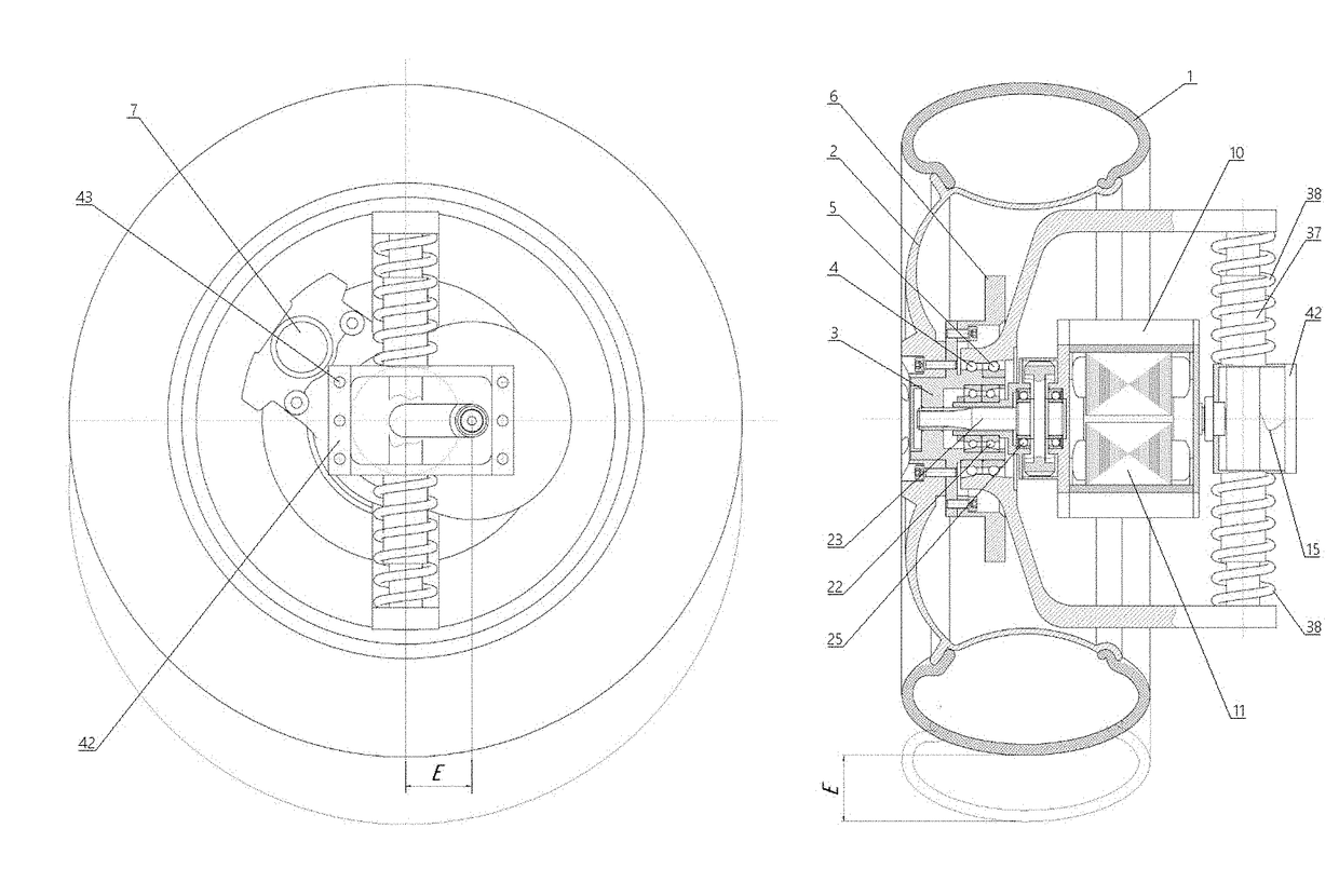
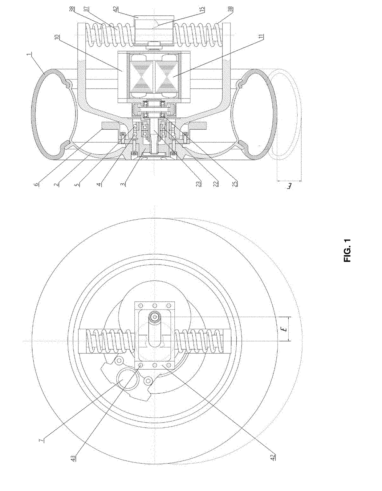
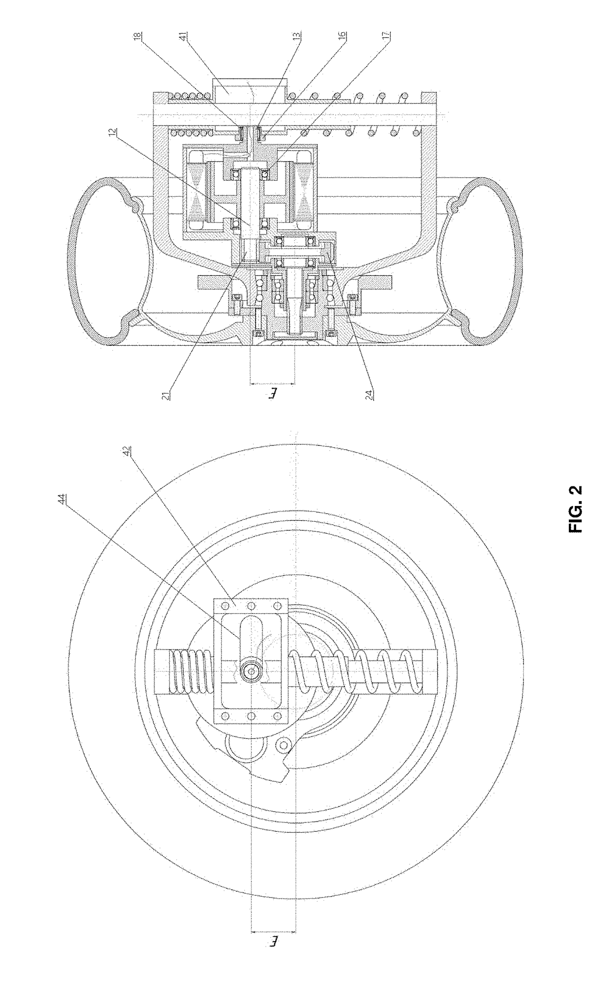
[0031]FIGS. 1-3 show the motor wheel according to the preferred embodiment of the present invention. The motor wheel comprises a wheel, an electric motor and a reduction gear formed by an oil-filled single gear reducer with parallel axes spaced apart from each other by a distance E.

[0032]The wheel comprises a tire 1, a wheel rim 2 with the tire 1 mounted thereon, a wheel hub 3 fixedly coupled with the rim 2 by means of a bolt coupling, two hub bearings 4, 5 mounted on the hub 3, a brake disc 6 coaxially coupled with the hub 3 by means of a bolt coupling, and a brake cylinder 7 for forcing brake shoes (not shown) against the brake disc 6 to provide vehicle braking.

[0033]The electric motor of the motor wheel comprises an electric motor case 10 with an electric motor stator 11 and an electric motor rotor received therein. The rotor comprises an electric motor rotor shaft 12 rotatably mounted in bearings 17. Electric current for operation of the electric motor is supplied via a conducto...


PUM


Abstract

The present invention relates to a motor wheel for a vehicle and a vehicle comprising the motor wheel. The motor wheel comprises a wheel, an electric motor, a reduction gear transmitting rotation from the electric motor to the wheel, and a dampening structure connecting the wheel to a vehicle bearing member. The electric motor comprises an electric motor case. The reduction gear comprises a reduction gear case coupled to the electric motor case and rotatably mounted within the wheel hub. The electric motor case is connected to the bearing member of the vehicle and is displaceable relative to the bearing member. The invention improves dynamic properties to the vehicle, reduces vibrations transmitted to the vehicle body, and provides a more comfortable drive.

Description

FIELD OF THE INVENTION[0001]The present invention generally relates to transport engineering, particularly, to electric motor wheels for electric and hybrid electric wheeled vehicles.BACKGROUND OF THE INVENTION[0002]Transport engineering is one of the most technically developed and ever growing industries. One of the industry development trends deals with replacing combustion engines powering most conventional vehicles with alternative drives. Currently attention is focused on hybrid electric vehicles and electric vehicles driven by eco-friendly electric motors and motor wheels.[0003]Hybrid electric vehicles and electric vehicles driven by electric motor wheels have a number of advantages over conventional vehicles using combustion engines. Such advantages include fewer complex and heavy transmission gears between the motor and the wheel (clutch, transmission, drive shafts and differentials), improved dynamics, maneuverability, fuel efficiency, and road safety. However, conventional...

Claims


Application Information

Patent Timeline
IPC IPC(8): B60K1/02B60K7/00
CPCB60K7/00B60K1/02B60G3/145B60K7/0007B60K17/043B60G2300/50B60G2300/37B60G2204/30B60G2204/182B60G2204/4232B60G2206/50B60K2007/0061B60K2007/0053F16F7/00
Inventor DOLGOV, LEONID VIKTOROVICHDOROSHENKO, ALEKSANDR NIKOLAEVICHTISHIN, ALEKSANDR METTALINOVICH
Owner OBSHCHESTVO S OGRANICHENNOI OTVETSTVENNOSTIU AMT
Why Eureka
Try Eureka