Self-Priming Pump

a self-priming pump and pump body technology, applied in the direction of priming pumps, machines/engines, liquid fuel engines, etc., can solve the problems of unappealing shaft constriction concept, and achieve the effect of simple design, easy production, and enhanced modular system advantages

Active Publication Date: 2018-03-01
GEA TUCHENHAGEN GMBH
View PDF14 Cites 1 Cited by
  • Summary
  • Abstract
  • Description
  • Claims
  • Application Information

AI Technical Summary

Benefits of technology

[0016]According to another development, the shaft section is formed on the second impeller. As additional advantages, this makes the pump easy to produce and makes it possible to create a modular system of self-priming and non-self-priming pumps in which the different types have many equivalent parts.
[0017]Another development refers to the connection of the impellers. The shaft section is accordingly shaped so that it accommodates a threaded section of a drive shaft bearing the first impeller. This is an advantageously simple design that moreover enhances the advantages of a modular system.
[0018]One development of the pump in the context of this invention is that the first impeller has a first clamping surface that interacts with the second clamping surface formed on the second impeller, and a clamping force is introduced into the first impeller via the clamping surfaces to clamp the first impeller on a cone frustum that is formed on a driveshaft that bears the first impeller. This is a simple, economical design that advantageously causes the two impellers to be attached at the same time.
[0019]According to a subsequent development, it is proposed that the second impeller comprises a helical blade arranged on a cylinder. This means that the second impeller is easy and economical to produce, for example according to DE 20 2004 013 752 U1.
[0020]The pumping effect of the pump stage with the at least one helical blade can be further improved when the blade has an extension on its end facing the shaft section.
[0021]For the aforementioned uses in a hygienic to aseptic context, it is advantageous to design the pump so that the first impeller is a part of a normally priming centrifugal pump.

Problems solved by technology

These achieved advantages outweigh the disadvantage with regard to the stability of the second impeller that results from the constriction and that initially makes the concept of a shaft constriction unappealing.

Method used


Image

  • Self-Priming Pump
  • Self-Priming Pump
  • Self-Priming Pump

Examples


Embodiment Construction

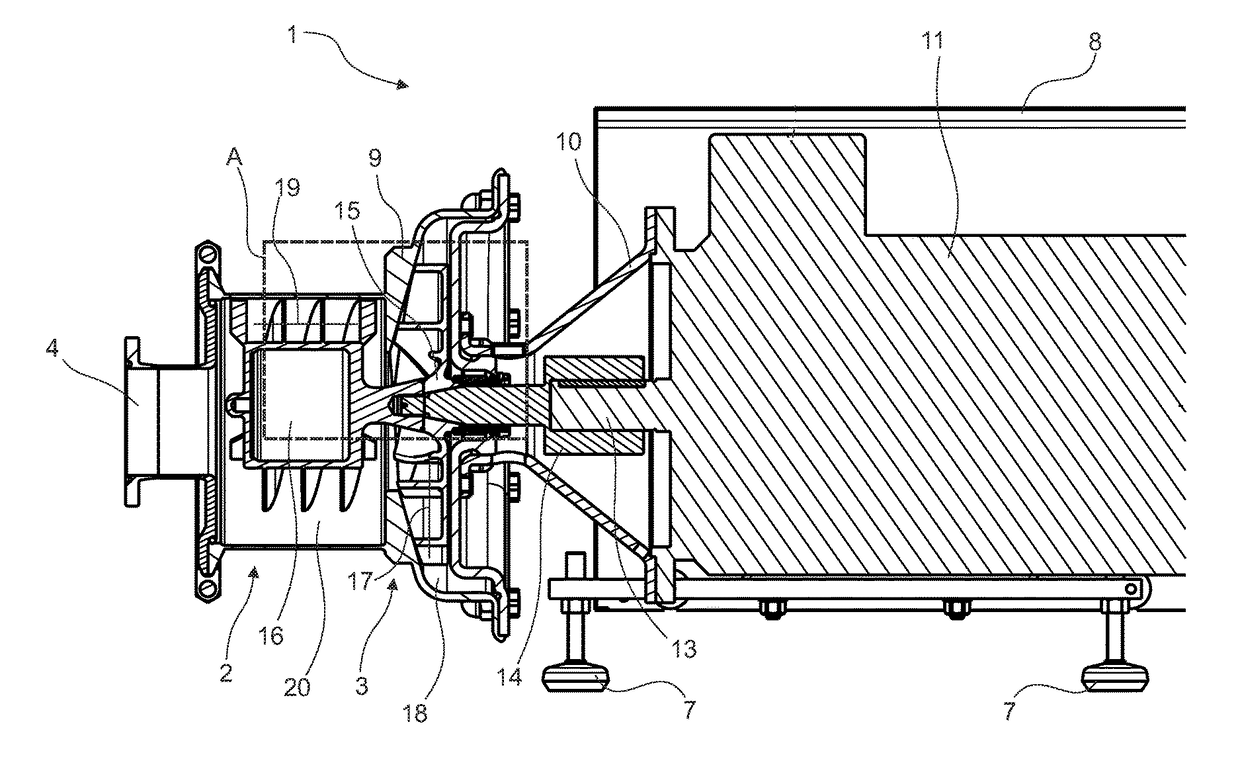
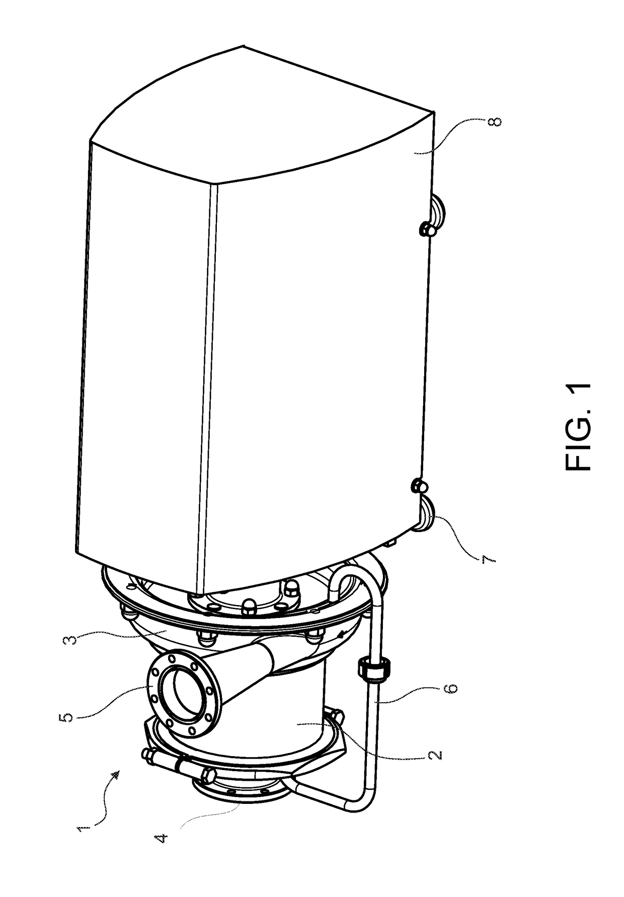
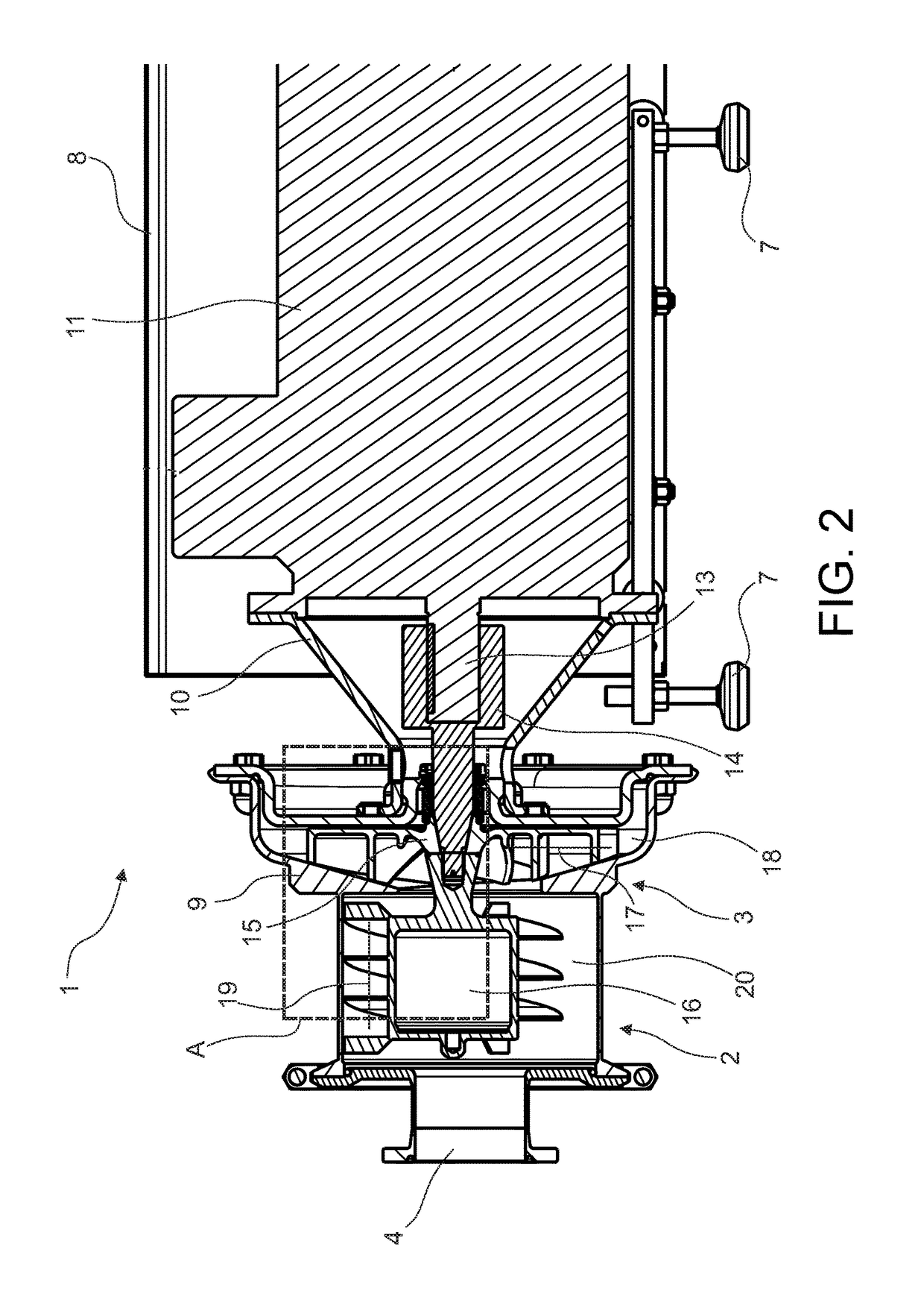
[0029]FIG. 1 shows a self-priming rotary pump 1 in a perspective representation. This rotary pump 1 comprises a liquid ring pump stage 2 and a normally priming centrifugal pump 3. The liquid ring pump stage 2 is assigned an inlet 4 of the self-priming rotary pump 1. Fluid, especially liquid to which gas may be added, enters through the inlet 4 of the rotary pump 1 and initially passes into the liquid ring pump stage 2. Then the fluid is transferred to the centrifugal pump 3. The fluid ejected from there leaves the self-priming rotary pump 1 through the outlet 5. A return line 6 branches from the centrifugal pump 3. The fluid flows through this return line 6 from the rotary pump 1 back into the liquid ring pump stage 2 and is available there to form the liquid ring even when the rotary pump 1 is starting.

[0030]The self-priming rotary pump 1 rests on feet 7 and possesses a cover 8 under which drive and control means are located, wherein the pumping effect of the self-priming rotary pu...


PUM


Abstract

A self-priming pump is described that has a housing, an inlet, and an outlet. A first impeller has a first pump section that is arranged in a first chamber, and a second impeller has a second pump section that is arranged in a second chamber. A shaft section is provided between the pump sections, and has a shaft end and penetrates an opening in a housing wall. To improve the net positive section head of the pump, the shaft section between a constriction and the shaft end is formed to taper from the shaft end toward the constriction, and the first impeller and shaft section between the constriction and first pump section has a smooth contour.

Description

TECHNICAL FIELD[0001]The invention relates to a self-priming pump.BACKGROUND[0002]Self-priming pumps are known in the prior art and have been used for many years successfully in the processing industry. In this context, the processing industry means in particular the beverage industry, food industry, pharmaceuticals and biochemistry.[0003]Such pumps are for example designed as self-priming rotary pumps. A first chamber and second chamber in each of which an impeller is arranged can be provided between the inlet and the outlet of such a rotary pump. Each impeller is part of a pump stage, wherein the pump stage closer to the inlet generates the self-priming feature.[0004]A first self-priming rotary pump of this kind is proposed in EP 1 191 228 A2. Another self-priming pump is described in DE 10 2007 032 228 A1.[0005]In addition to the rotary pump stage, these two rotary pumps possess a liquid ring pump stage that receives the fluid to be pumped directly from the inlet of the rotary pu...

Claims


Application Information

Patent Timeline
Patent Type & Authority Applications(United States)
IPC IPC(8): F04D29/22F04D1/06F04D3/02F04D9/02F04D29/043
CPCF04D29/2277F04D1/06F04D3/02F04D9/02F04D29/043F04D9/04F04D9/041F04D29/62
Inventor DIRKS, STEPHANPAWLIK, MARKUS
Owner GEA TUCHENHAGEN GMBH
Why Eureka
Try Eureka