Shared oil system arrangement for an engine component and a generator

a technology of engine components and oil systems, which is applied in the direction of filtration separation, lubricant mounting/connection, separation process, etc., can solve the problems of affecting the cooling effect of gas turbine engines. , to achieve the effect of reducing the second oil flow

Active Publication Date: 2018-03-08
PRATT & WHITNEY CANADA CORP
View PDF6 Cites 11 Cited by
  • Summary
  • Abstract
  • Description
  • Claims
  • Application Information

AI Technical Summary

Benefits of technology

[0005]In one aspect, there is provided a method of distributing oil within a gas turbine engine, the method comprising directing a first oil flow from an oil source to an engine component of the gas turbine engine and back to the oil source; directing a second oil flow from the oil source to a generator driven by the gas turbine engine an...

Problems solved by technology

However, this arrangement may expose the engine oil system to contamination from the generator.
In some instances, large quantities of contaminant...

Method used


Image

  • Shared oil system arrangement for an engine component and a generator
  • Shared oil system arrangement for an engine component and a generator
  • Shared oil system arrangement for an engine component and a generator

Examples


Embodiment Construction

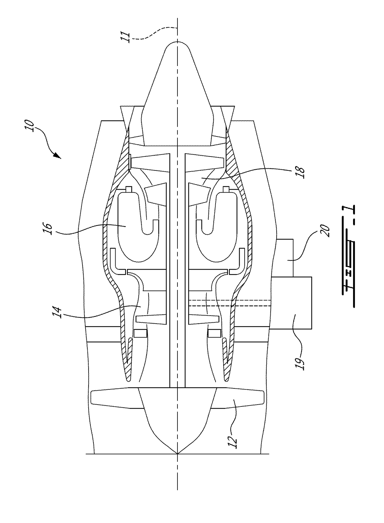
[0012]FIG. 1 illustrates a gas turbine engine 10 of a type preferably provided for use in subsonic flight, generally comprising in serial flow communication a fan 12 through which ambient air is propelled, a compressor section 14 for pressurizing the air, a combustor 16 in which the compressed air is mixed with fuel and ignited for generating an annular stream of hot combustion gases, and a turbine section 18 for extracting energy from the combustion gases. The turbine engine 10 includes several components that require cooling and / or lubrication, including, but not limited to, bearings, gears, seals, and the like. In the embodiment shown, one of these components is a reduction gearbox 19. The gearbox 19 includes a fluid circuit (not shown), for example an oil circuit, for cooling and / or lubricating parts of the gearbox 19 such as bearing chambers. The fluid circuit can also be used for sealing purposes. In the embodiment shown, the gearbox 19 is provided as a reduction gearbox.

[0013...


PUM

PropertyMeasurementUnit
Temperatureaaaaaaaaaa
Pressureaaaaaaaaaa
Flow rateaaaaaaaaaa

Abstract

A method of distributing oil to a component within a gas turbine engine includes directing a first oil flow from an oil source to an engine component and back to the oil source, directing a second oil flow from the oil source to a generator driven by the engine and back to the oil source, monitoring a parameter of the second oil flow downstream of the generator and upstream of the oil source, detecting a contaminant in the second oil flow based on the parameter, and reducing the second oil flow to the generator when the contaminant is detected without reducing the first oil flow to the engine component. A shared oil system for a component of a gas turbine engine and a generator driven by the gas turbine engine is also discussed.

Description

CROSS-REFERENCE TO RELATED APPLICATIONS[0001]This application claims priority from provisional U.S. application No. 62 / 384,442 filed on Sep. 7, 2016, the entire contents of which are incorporated by reference herein.TECHNICAL FIELD[0002]The application relates generally to the cooling and lubrication of gas turbine engines and, more particularly, to a shared oil system for an engine component and a generator driven by the engine.BACKGROUND OF THE ART[0003]Gas turbine engines may drive generators for generating electrical power for aircraft use. These generators are generally air or oil cooled. For oil cooled generators, it can be preferential to integrate an oil system for the generator with an oil system for an engine component of the engine into a shared engine oil system. In the shared engine oil system, oil return lines from the generator and the engine component return the oil into the engine oil system. However, this arrangement may expose the engine oil system to contaminatio...

Claims


Application Information

Patent Timeline
IPC IPC(8): F01M11/10F01D15/10F01D25/20F01M1/02F01M11/03B01D35/143B01D29/60B01D29/44
CPCF01M11/10F01D15/10F01D25/20F01M1/02F01M11/03B01D35/1435B01D2201/54B01D29/606B01D29/608B01D29/44F05D2220/32F05D2260/98B01D29/601F01M1/10F16N29/04F05D2220/50F05D2220/76F05D2260/607F16N2250/00F16N2250/04F16N2250/06F16N2250/08F16N2270/70F16N2200/04F16N7/40
Inventor WADDLETON, DAVIDMCGUIRE, DANIEL MATTHEW
Owner PRATT & WHITNEY CANADA CORP
Why Eureka
Try Eureka