Automatic system calibration method of x-ray ct
a technology of automatic system calibration and x-ray computed tomography, applied in the field of medical imaging, can solve problems such as automatic system calibration
- Summary
- Abstract
- Description
- Claims
- Application Information
AI Technical Summary
Benefits of technology
Problems solved by technology
Method used
Image
Examples
example 1
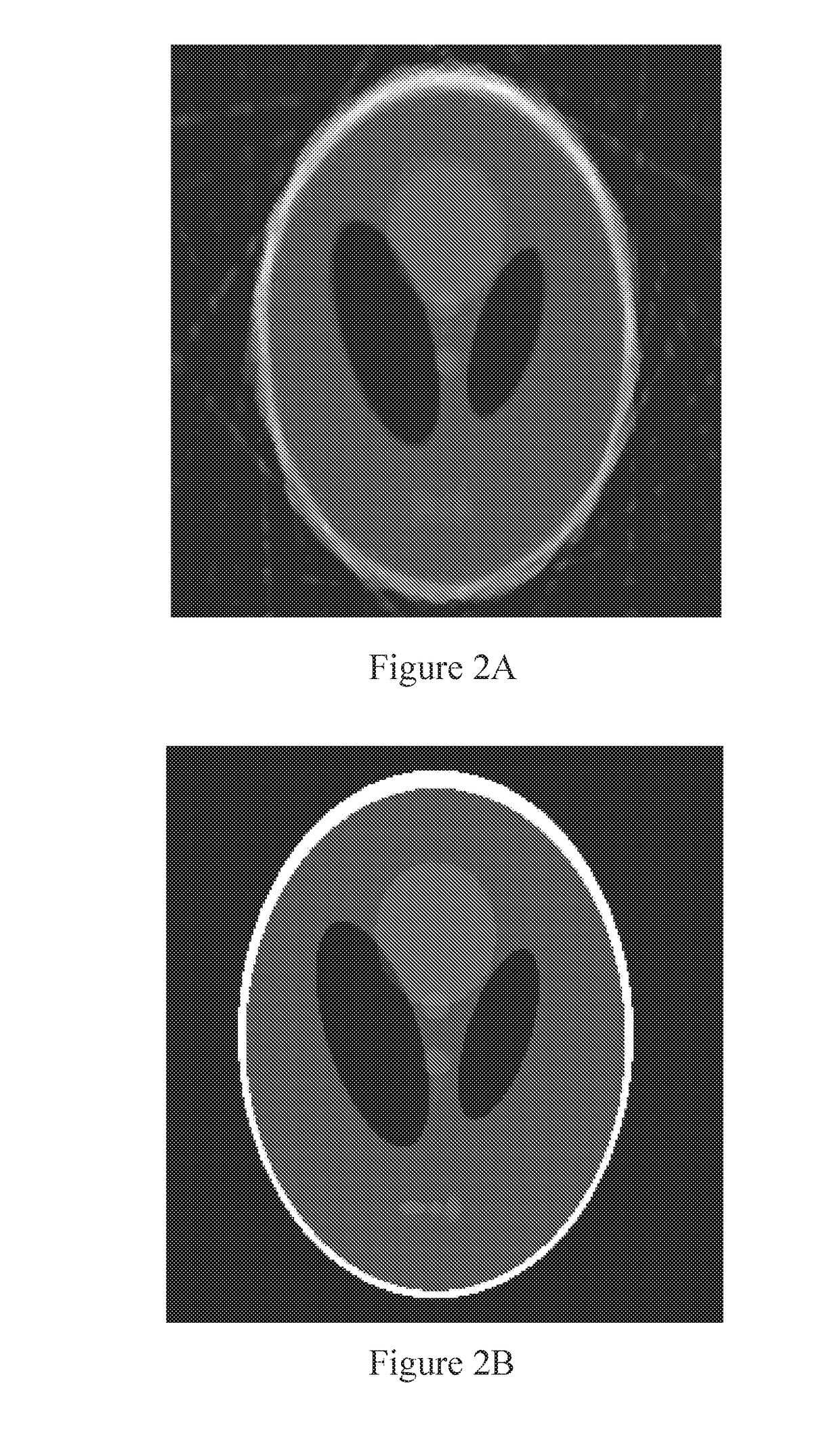
[0160]The LLE-based calibration approach was evaluated using an abdomen image phantom from a clinic, shown in FIG. 15. The size of the abdomen phantom was 512×512. With this phantom, projection data with angular and other geometric errors were generated. Then, the algorithm described herein was applied to the projection data with geometric parameter errors. The algorithm was tested in a rigid patient motion problem. The computational environment was MatLab 2010a on a computer with an Intel Core 2 Duo E7600 CPU @3.06 GHz, 4.00 GB RAM, and a 64-bit OS.
[0161]To evaluate reconstructed images, UQI was used. Also, geometric calibration results were quantified with the average angular error θerror, parametric error PError, and average object coordinate offsets x and y.
[0162]The image reconstruction process was performed using OS-SART with TV regularization. As the reconstruction and calibration iteration stop criteria, satisfactory UQI values were monitored for in both the image and projec...
example 2
[0169]The calibration algorithm discussed herein was applied in a case of real projection data with geometric parameter errors. The nominal SOD and ODD values were both 38 cm, the number of detector elements was 1024, and the length of the detector was 13.0048 cm. The number of projection angles was 900 in the angular range [0°, 360°]. An object was on the rotation stage while the rotation center was not on the line between the X-ray source and the detector center, as shown in FIG. 20, where the red spot (spot contained within the shaded circle) was the rotation center not on the system origin. Therefore, the algorithm was used to calibrate the rotation center offset. The sampling range was [−1 cm, 1 cm] with a sampling step of 0.05 cm. The number of nearest neighbors was 2. The UQI stopping threshold was 0.9 for reconstruction and 0.6 for calibration.
[0170]FIG. 21A shows the reconstructed image before any compensation. FIG. 21B shows the reconstructed image depicted in FIG. 21A aft...
example 3
[0172]Calibration as discussed herein was tested for a situation involving rigid patient motion. As discussed, rigid patient motion can be represented as object x-coordinate offset error, object y-coordinate offset error, and projection angle error. Rigid patient motion calibration was simulated with an abdomen phantom. The number of projection angles and other parameters were the same as in Example 1. The object x-coordinate offset error and object y-coordinate offset error were all randomly selected within the range of [−1 cm, 1 cm], and the projection angle errors were randomly chosen within the range of [−1°, 1°].
[0173]The calibration was in the following sequence: object x-coordinate offset; object y-coordinate offset; and projection angle. The sampling rates for the parameters were 0.05 cm, 0.05 cm, and 0.1°, respectively. The sampling ranges were [−1 cm, 1 cm], [-1 cm, 1 cm], and [−1°, 1°], respectively. The number of nearest neighbors was K=2. The UQI stop value for reconstr...
PUM
 Abstract
Description
Claims
Application Information
 - R&D
- Intellectual Property
- Life Sciences
- Materials
- Tech Scout
- Unparalleled Data Quality
- Higher Quality Content
- 60% Fewer Hallucinations
Browse by: Latest US Patents, China's latest patents, Technical Efficacy Thesaurus, Application Domain, Technology Topic, Popular Technical Reports.
© 2025 PatSnap. All rights reserved.Legal|Privacy policy|Modern Slavery Act Transparency Statement|Sitemap|About US| Contact US: help@patsnap.com


