Braking-force-maintaining device for vehicle and electric braking device for vehicle
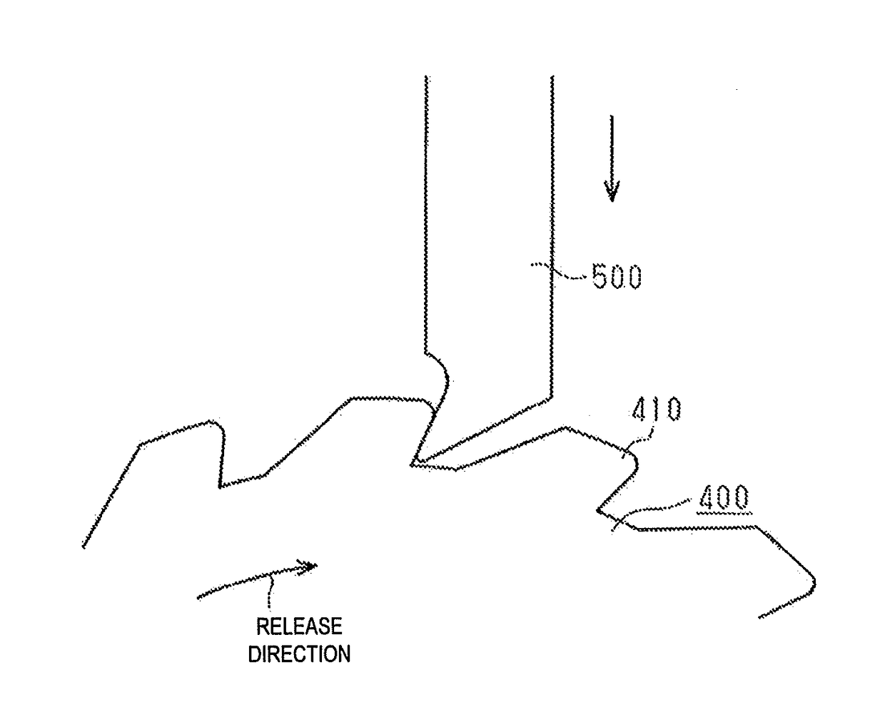
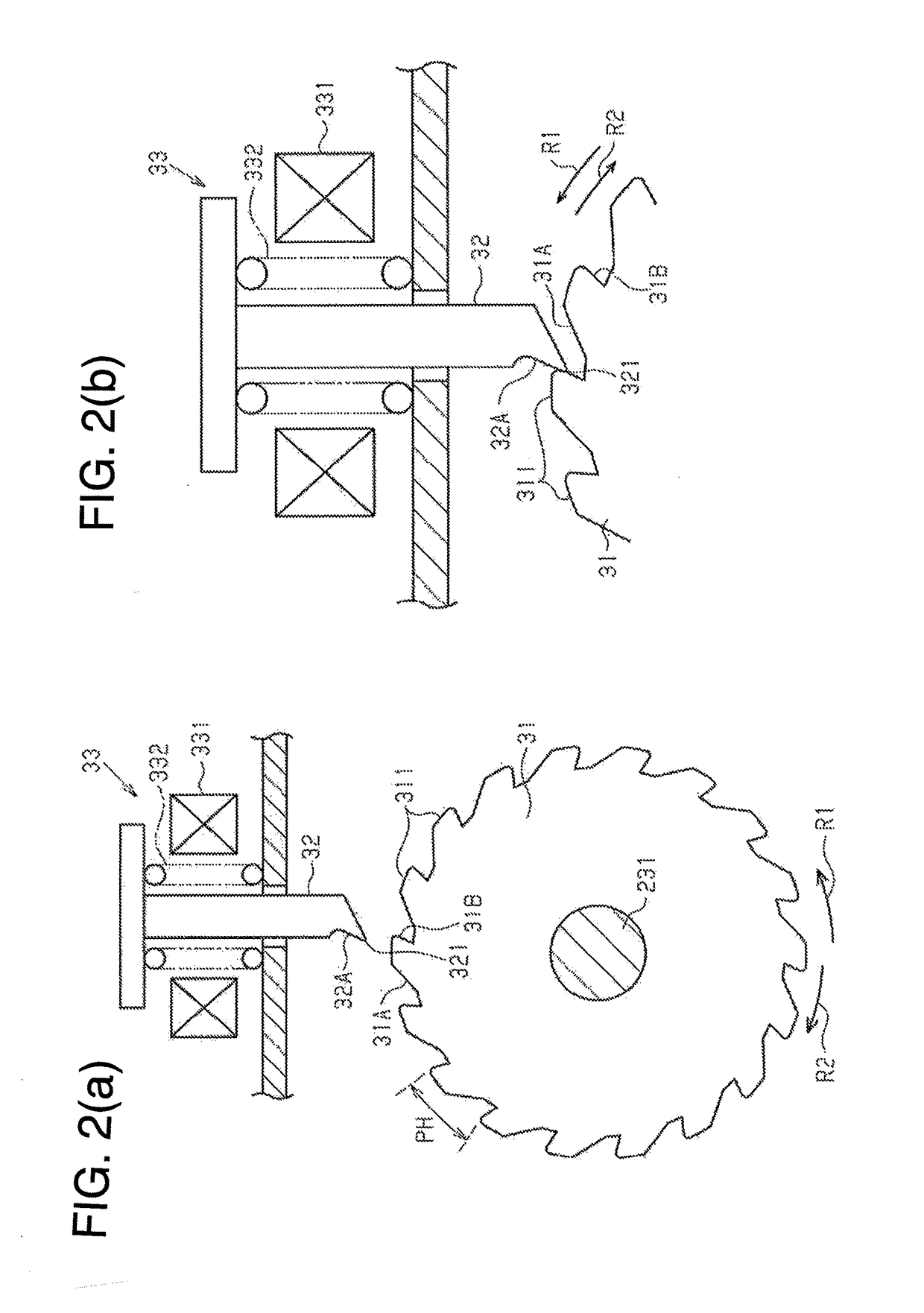
a technology of braking force and braking device, which is applied in the direction of braking system, mechanical equipment, transportation and packaging, etc., can solve the problem that the pawl member cannot regulate the rotation of the ratchet gear in the release direction in some cases, and achieve the effect of suppressing the decrease of braking for
- Summary
- Abstract
- Description
- Claims
- Application Information
AI Technical Summary
Benefits of technology
Problems solved by technology
Method used
Image
Examples
first embodiment
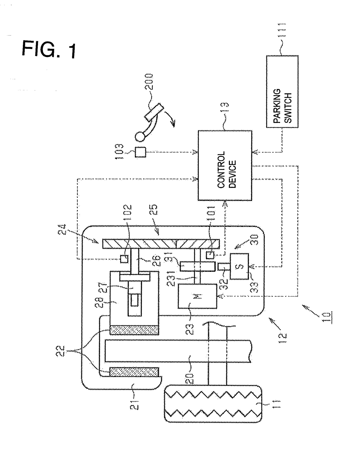
[0041]Hereinafter, a first embodiment embodying a braking-force-maintaining device for a vehicle and an electric braking device for a vehicle will be described with reference to FIGS. 1 to 5.
[0042]As shown in FIG. 1, an electric braking device 10 for a vehicle includes an electrically operated brake actuator 12 provided for each wheel 11 and a control device 13 for controlling the brake actuator 12. For example, the electric braking device 10 applied to a vehicle having four wheels 11 includes a total of four brake actuators 12.
[0043]The brake actuator 12 is a disc-type electric actuator and includes a brake disc 20 which is an example of a rotor integrally rotating with the wheel 11, and a brake caliper 21 supported by a vehicle body. The brake caliper 21 supports a pair of brake pads 22 disposed on both sides of the brake disc 20 in a vehicle width direction which is the horizontal direction in the drawing. These brake pads 22 correspond to an example of “friction member”. The bra...
second embodiment
[0119]Hereinafter, a second embodiment embodying an electric braking device for a vehicle and a braking-force-maintaining device for a vehicle will be described with reference to FIGS. 7 and 8. In the following description, portions different from the first embodiment will be mainly described, and the same member configurations as in the first embodiment are denoted by the same reference signs, and a redundant description will be omitted.
[0120]A rotational angle detection sensor 101 provided in an electric braking device 10 for a vehicle according to the present embodiment can detect an absolute rotational angle Mka of a ratchet gear 31. Therefore, before energizing a solenoid 33 to press a pawl member 32 against the ratchet gear 31, it can be determined whether or not the rotational angle Mka of the ratchet gear 31 is substantially equal to a semi-engaging rotational angle MkaA.
[0121]Therefore, with reference to FIG. 7, operations of the electric braking device 10 for a vehicle acc...
third embodiment
[0148]Next, a third embodiment embodying an electric braking device for a vehicle and a braking-force-maintaining device for a vehicle will be described with reference to FIGS. 9 and 10. In the following description, portions different from the first and second embodiments will be mainly described, and the same member configurations as in the first and second embodiments are denoted by the same reference signs, and a redundant description will be omitted.
[0149]A rotational angle detection sensor 101 provided in an electric braking device 10 for a vehicle according to the present embodiment can detect an absolute rotational angle Mka of a ratchet gear 31. Therefore, when the braking force applied to a wheel 11 reaches a required braking force BPT, it can be determined whether or not the rotational angle Mka of the ratchet gear 31 is substantially equal to a semi-engaging rotational angle MkaA.
[0150]Therefore, with reference to FIG. 9, operations of the electric braking device 10 for ...
PUM
 Abstract
Description
Claims
Application Information
 - R&D
- Intellectual Property
- Life Sciences
- Materials
- Tech Scout
- Unparalleled Data Quality
- Higher Quality Content
- 60% Fewer Hallucinations
Browse by: Latest US Patents, China's latest patents, Technical Efficacy Thesaurus, Application Domain, Technology Topic, Popular Technical Reports.
© 2025 PatSnap. All rights reserved.Legal|Privacy policy|Modern Slavery Act Transparency Statement|Sitemap|About US| Contact US: help@patsnap.com


