
Pwm modulator

a modulator and modulator technology, applied in the direction of low frequency amplifiers, amplifiers, semiconductor devices/discharge tubes, etc., can solve the problems of non-ideal factors such as noise and distortion, causing harmful effects on other circuits, and causing defects of class-ads

Active Publication Date: 2018-03-15
KK TOSHIBA
View PDF2 Cites 17 Cited by
  • Summary
  • Abstract
  • Description
  • Claims
  • Application Information

AI Technical Summary

Benefits of technology

The patent text describes a PWM modulator that is used in an audio amplifier such as an in-car audio amplifier. The PWM modulator uses a sawtooth waveform to modulate the pulse width of the sound signal. The text describes the advantages and disadvantages of using a Class-AD PWM modulator and a Class-BD PWM modulator. The technical effect of the invention is to provide a PWM modulator that can achieve a high S / N ratio and minimize the impact of non-ideal factors, such as a carrier generator and a demodulation filter, on the sound signal quality. The invention includes a first comparator and a second comparator that compare input signals with carriers and output comparison results, which are then switched in a cycle to improve the quality of the sound signal.

Problems solved by technology

Accordingly, in the Class-BD, unnecessary radiation by the in-phase output from the PWM modulator is generated, and generates a harmful effect on other circuits.
However, even if a system in which common-mode noise is reduced by employing the Class-AD is constructed in in-car application, or the like, there is a possibility that the following defects of the Class-AD may occur.
Actually, a non-ideal factor such as noise and distortion is added to the carrier.
In the case where noise is mixed or distortion occurs in the carrier, in the Class-AD, there is a problem that waveform distortion occurs in the ΔAD signal, S / N degrades, and offset also occurs.
However, there is a case where the carrier has a non-ideal waveform having non-linearity with respect to time.
However, this countermeasure is not effective as a countermeasure against harmful effects generated by the non-ideal factor of the carrier generator because it is difficult to set a large loop gain at the class D amplifier due to band constraint.
It is now assumed that carrier noise and carrier distortion occur in the saw tooth wave carrier.

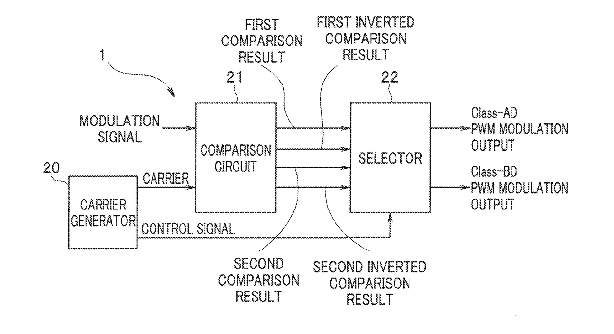
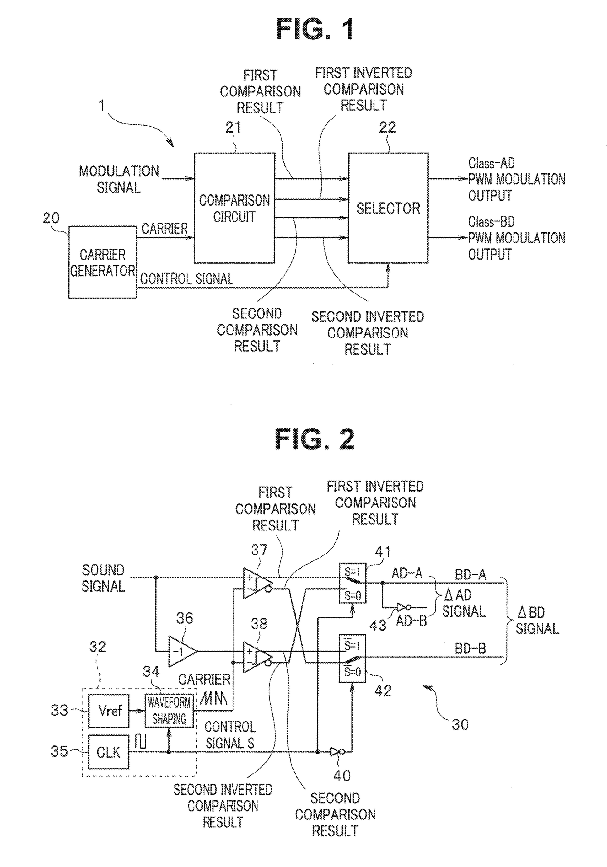
Method used


Image

  • Pwm modulator
  • Pwm modulator
  • Pwm modulator

Examples


Embodiment Construction

[0020]A PWM modulator according to an embodiment includes a first comparator configured to compare a first input signal with a first carrier and output a comparison result, a second comparator configured to compare a second input signal with a second carrier and output a comparison result and a selector configured to output the comparison result while switching between the comparison result of the first comparator and the comparison result of the second comparator in a cycle according to a cycle of the first or the second carrier.

[0021]The embodiment will be described in detail below with reference to the drawings.

[0022]FIG. 1 is a block diagram illustrating a PWM modulator 1 according to one embodiment of the present invention. Further, FIG. 2 is a circuit diagram illustrating a specific example of the PWM modulator in FIG. 1. Note that, while, in the embodiment, a sound signal will be described as an example of a modulation signal, the modulation signal is not limited to the sound...


PUM


Abstract

A PWM modulator according to an embodiment includes a first comparator configured to compare a first input signal with a first carrier and output a comparison result, a second comparator configured to compare a second input signal with a second carrier and output a comparison result, and a selector configured to output the comparison result while switching between the comparison result of the first comparator and the comparison result of the second comparator in a cycle according to a cycle of the first or the second carrier.

Description

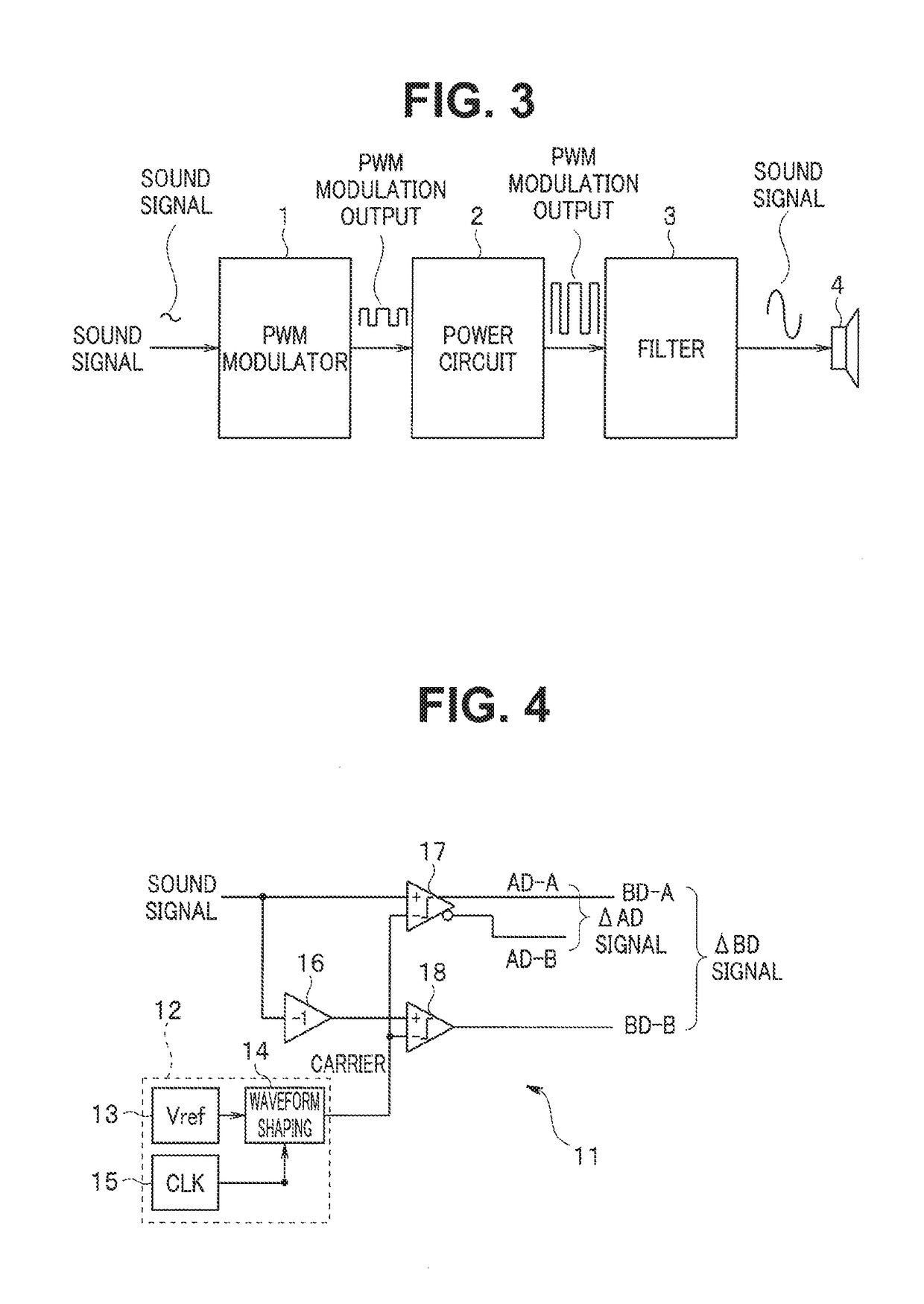
CROSS-REFERENCE TO RELATED APPLICATIONS[0001]This application is based upon and claims the benefit of priority from U.S. Provisional Application No. 62 / 385,422, filed on Sep. 9, 2016, the entire contents of which are incorporated herein by reference.FIELD[0002]Embodiments described herein relate generally to a PWM modulator.BACKGROUND[0003]In recent years, as an audio amplifier such as an in-car audio amplifier, a class D amplifier which employs a PWM modulator has been in widespread use. The PWM modulator, which is used as a switching converter, generates a PWM signal of a pulse width according to an amplitude of a sound signal in the class D amplifier.[0004]The PWM modulator modulates the pulse width of the sound signal by comparing the sound signal with a carrier of a saw tooth wave (one side edge) or a triangle wave (both side edges). The PWM modulator is used in Class-AD in which a binary switching waveform is obtained as a result of modulation of the pulse width or in Class-BD...

Claims


Application Information

Patent Timeline
Patent Type & Authority Applications(United States)
IPC IPC(8): H03K7/08H03F3/183
CPCH03K7/08H03F3/183H03F2200/351H03F2200/171H03F2200/78H03F2200/03H03F3/2171H03F1/04H04B1/56
Inventor YAMAUCHI, AKIRAFUJII, TOSHIKAZU
Owner KK TOSHIBA
Learn More