Circuit Arrangement For Reducing A Magnetic Unidirectional Flux Component In The Core Of A Transformer

Active Publication Date: 2018-03-22
SIEMENS ENERGY GLOBAL GMBH & CO KG
View PDF0 Cites 0 Cited by
  • Summary
  • Abstract
  • Description
  • Claims
  • Application Information

AI Technical Summary

Benefits of technology

The patent describes a way to control the movement of electric current in a circuit. By using two different types of impedance, the circuit can adjust the inductance of each branch of the circuit separately. This provides greater control over the overall behavior of the circuit.

Problems solved by technology

In circuit engineering terms an ohmic resistor would also be conceivable although its active-power losses would be a drawback.

Method used


Image

  • Circuit Arrangement For Reducing A Magnetic Unidirectional Flux Component In The Core Of A Transformer
  • Circuit Arrangement For Reducing A Magnetic Unidirectional Flux Component In The Core Of A Transformer

Examples


Embodiment Construction

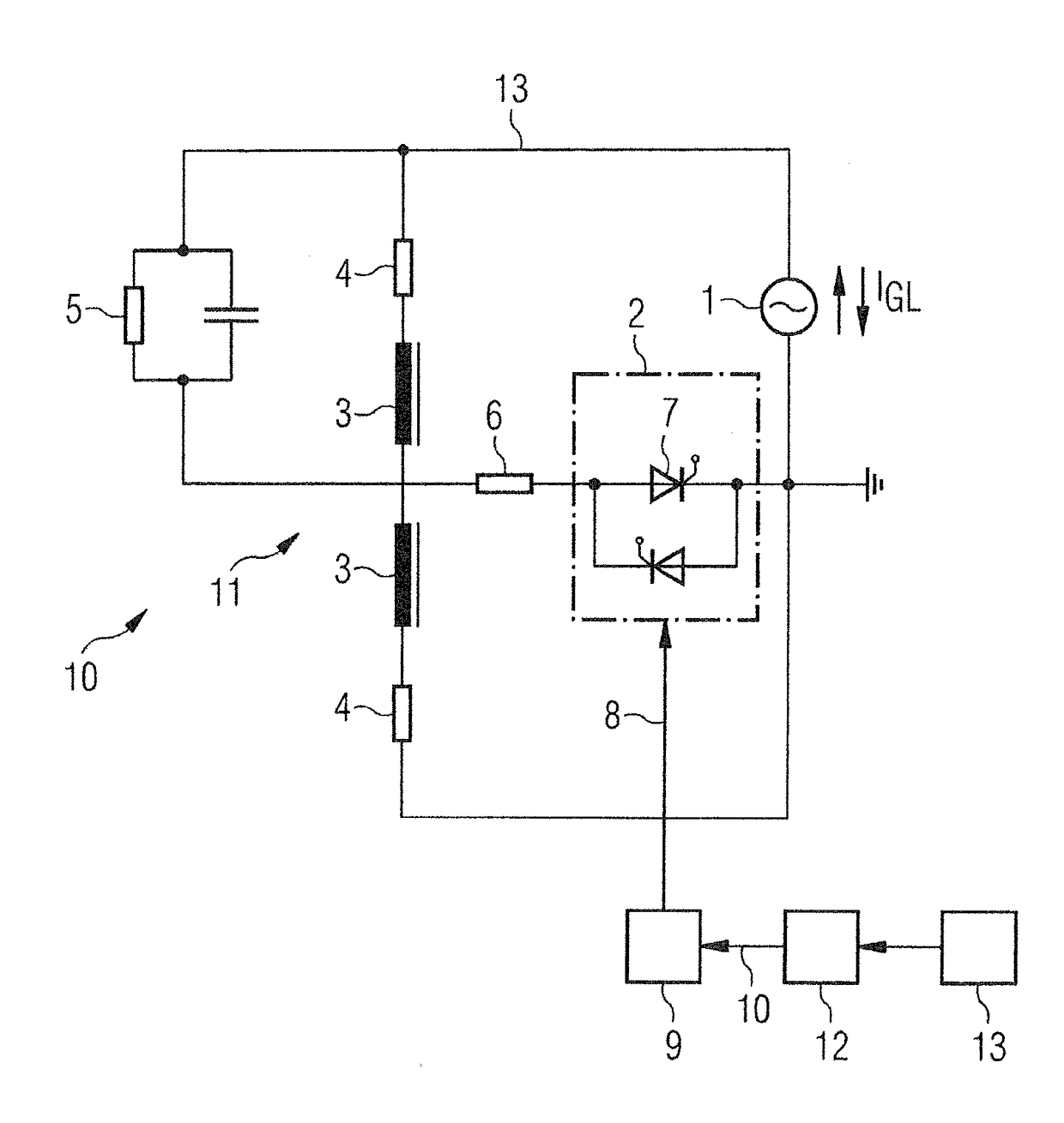
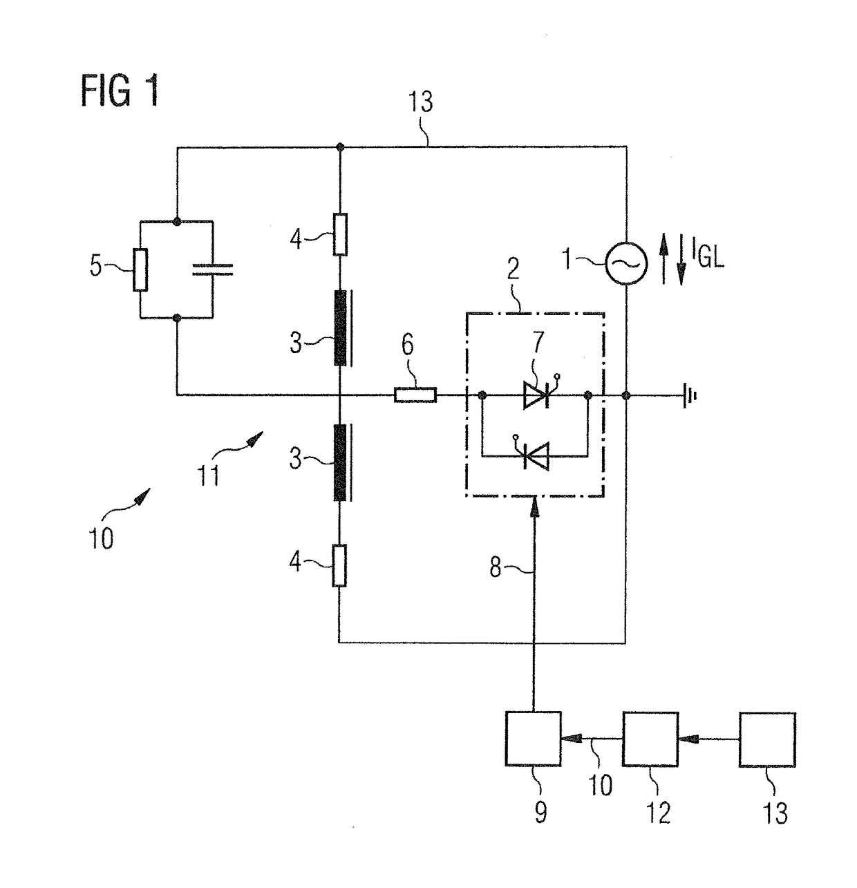
[0021]The FIGURE a shows simplified schematic block diagram of a switching device 10 in accordance with an exemplary embodiment of the invention. The switching device 10 consists essentially of an inductive voltage divider 11 that consists of a first impedance, impedance 3, and a second impedance, impedance 3′. In this regard, the first impedance 3 is connected in a current path 13 in series with the semiconductor switching device 2 and the compensation coil 1. In the FIGURE the compensation coil 1 is drawn with the symbol for a voltage source. The voltage induced in the compensation coil 1 forms the total voltage of the voltage divider 3, 3′. The first and second impedances 3, 3′ are arranged on a magnetic core and differ in terms of their number of turns. By a suitable implementation of the first and second impedances 3, 3′, for example, by a suitable choice of the number of turns, the partial voltages at the inductive resistances 3 or 3′ respectively can be structured correspondi...


PUM


Abstract

A circuit arrangement for reducing a magnetic unidirectional flux component in a core of a transformer includes a measuring device that provides a sensor signal corresponding to the magnetic unidirectional flux component, a compensation coil magnetically coupled to the core of the transformer, and a semiconductor switching device which is electrically arranged in a current path in series with the compensation coil to feed a current into the compensation coil, such that current is directed opposite the unidirectional flux component, where the semiconductor switching device is controlled via a control signal provided by a controller, and includes an inductive voltage divider having a first impedance component arranged in a current circuit in series with the compensation coil and the semiconductor switching device and a second impedance component arranged in parallel with the semiconductor switching device, where the first impedance component is connected in parallel with a parallel resonant circuit.

Description

CROSS-REFERENCE TO RELATED APPLICATIONS[0001]This is a U.S. national stage of application No. PCT / EP2016 / 053617 filed 22 Feb. 2016. Priority is claimed on European Application No. 15162172.9 filed Apr. 1, 2015, the content of which is incorporated herein by reference in its entirety.1. FIELD OF THE INVENTION[0002]The invention relates to a circuit arrangement for reducing a magnetic unidirectional flux component in the core of a transformer, with a measuring device that provides a sensor signal corresponding to the magnetic unidirectional flux component, with a compensation coil that is magnetically coupled to the core of the transformer, with a semiconductor switching device that is electrically arranged in a current path in series with the compensation coil to feed a current into the compensation coil, the effect of which current being directed opposite to the unidirectional flux component, where the semiconductor switching device can be controlled via a control variable provided ...

Claims


Application Information

Patent Timeline
IPC IPC(8): H01F27/42H01F27/02
CPCH01F27/42H01F27/02G01R33/02H01F27/34H01F2029/143G05F1/32G05F1/33H01F27/25H01F27/38
Inventor HAMBERGER, PETER
Owner SIEMENS ENERGY GLOBAL GMBH & CO KG
Why Eureka
Try Eureka