Active phase switchable array

a switchable array and active phase technology, applied in the field of phase arrays, can solve the problems of increasing power loss, cost, control complexity,

Active Publication Date: 2018-03-22
NAT SUN YAT SEN UNIV
View PDF0 Cites 11 Cited by
  • Summary
  • Abstract
  • Description
  • Claims
  • Application Information

AI Technical Summary

Benefits of technology

[0006]The active phase switchable array of the present invention can detect the vital sign of the subject by the self-injection-locked mechanism of each of the antenna elements, and can produce the phase difference between the output signals of the antenna elements by the mutual-injection-locked mechanisms of the antenna elements to allow the active phase switchable array possess the capability of the beamforming for detecting the vital signs of multiple subjects simultaneously.

Problems solved by technology

The passive phase array 200 can form the beam with different direction, but this architecture needs more active control elements to control the signals, which increase the power loss, the control complexity and the cost.

Method used


Image

  • Active phase switchable array
  • Active phase switchable array
  • Active phase switchable array

Examples


first embodiment

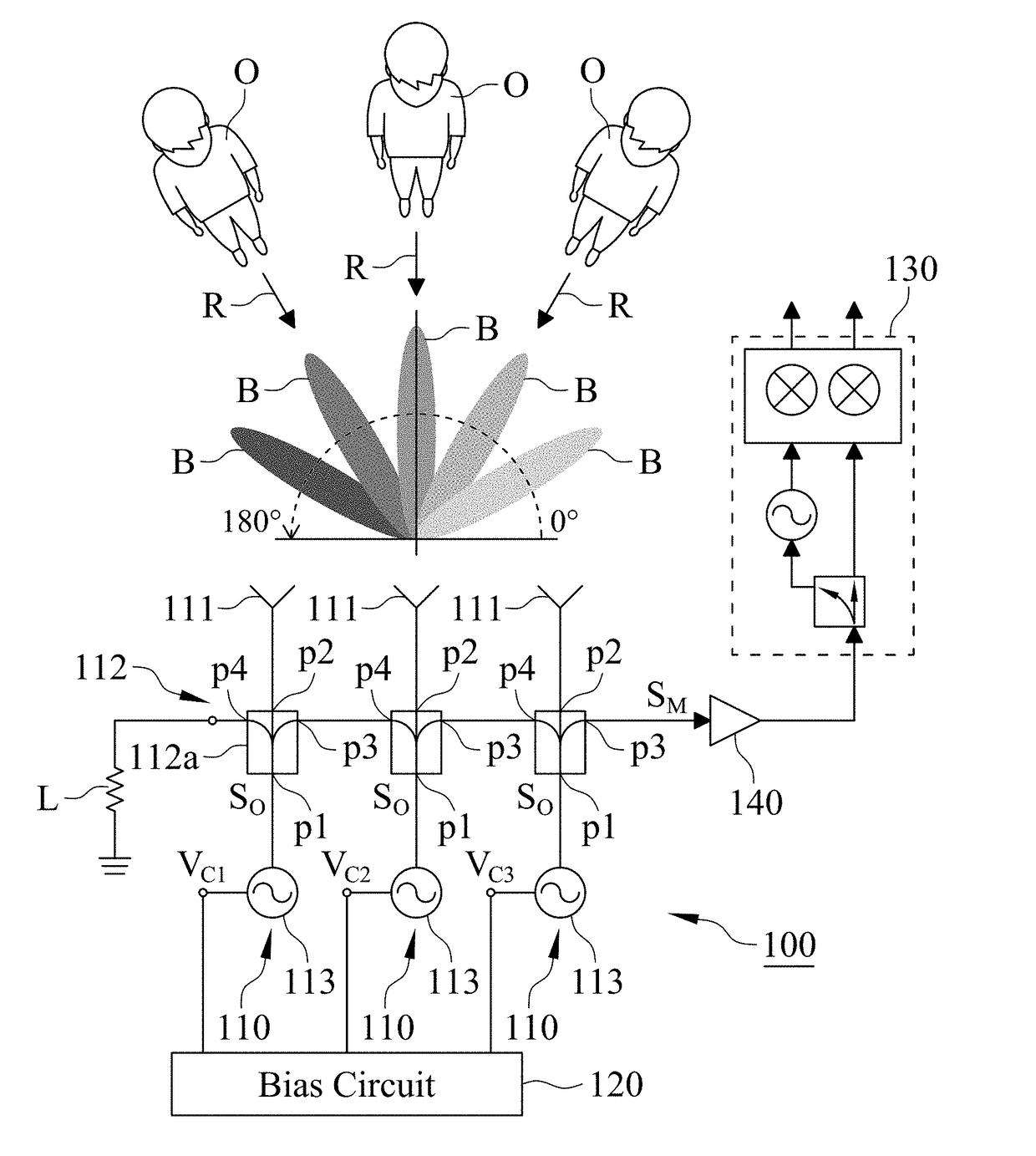
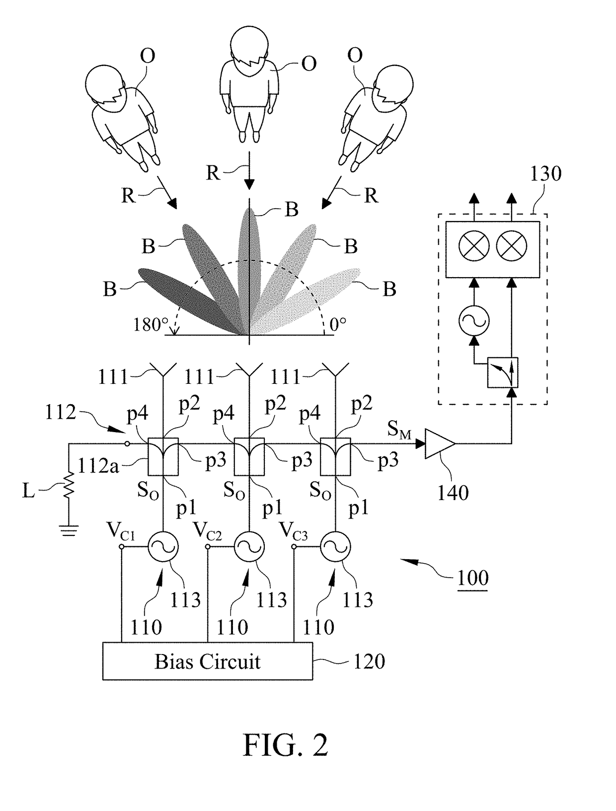
[0019]With reference to FIG. 2 which is a circuit diagram of an active phase switchable array 100 in accordance with the present invention, the active phase switchable array 100 includes a plurality of antenna elements 110, a bias circuit 120, a demodulation circuit 130 and an amplifier 140. The bias circuit 120 is coupled to the antenna elements 110, and the demodulation circuit 130 is coupled to one of the antenna elements 110 through the amplifier 140. In other embodiment, the amplifier 140 is not required when the output power of each of the antenna elements 110 or the sensitivity of the demodulation circuit 130 is high enough.

[0020]With reference to FIG. 2, the active phase switchable array 100 has three antenna elements 110 in the first embodiment. In the other embodiment, the active phase switchable array 100 can has two or more than three antenna elements 110. Each of the antenna elements 110 includes an antenna 111, a power coupling network 112 and an injection-locked oscil...

third embodiment

[0032]With reference to FIG. 10 which is provided to illustrate the MIL path of the ILOs 113 in the For simplicity, only the left and middle antenna elements 110 are used to explain the MIL path below. The output signals SO of the left ILO 113 is input to the input port pi of the left directional coupler 112b and output to the left second power splitter 112d through the second coupling port pc2, then injected into the middle ILO 113 via the middle first power splitter 112c and the middle directional coupler 112b. Moreover, the output signal SO of the ILO 113 of the middle antenna element 110 is also injected into the left ILO 113 through the middle directional coupler 112b, the middle first power splitter 112c, the left second power splitter 112d and the left directional coupler 112b. As a result, all of the ILOs 113 are operated in the MIL state. The mutual-injection-locked among the ILOs 113 can vary the phase difference between the output signals SO of the ILOs 113 to allow the ...


PUM


Abstract

An active phase switchable array includes a plurality of antenna elements and a bias circuit. Each of the radar elements includes an antenna, a power coupling network and an injection-locked oscillator (ILO), and each of the antenna elements is coupled with each other through the power coupling networks for operating the ILO of each of the antenna elements in self- and mutual-injection-locked states. The antenna elements in self-injection-locked state are utilized to detect the vital signs of subjects, and the antenna elements in mutual-injection-locked state are utilized to produce phase difference between the radiating signals of the antenna elements for forming a beam. As a result, the active phase switchable array can simultaneously detect the vital signs of multiple subjects.

Description

FIELD OF THE INVENTION[0001]This invention generally relates to a phase array, and more particularly to an active phase switchable array.BACKGROUND OF THE INVENTION[0002]Conventional phase array is applied in communication system or search radar, and includes an antenna array which can increase the signal intensity in a specific direction and decrease the signal intensity in other directions for beamforming by controlling the phase of the signals radiated from each antenna. The beam covering the target communication device or subject can decrease the beam influence on other devices or the influence of environment noise on the phase array for improving the communication or search capability.[0003]With reference to FIG. 1, a passive phase array 200 includes a plurality of antenna elements 210 and a transceiver module 220, wherein the antenna elements 210 are coupled to the transceiver module 220 by a power splitter. Each of the antenna elements 210 includes an antenna 211, an amplifie...

Claims


Application Information

Patent Timeline
Patent Type & Authority Applications(United States)
IPC IPC(8): H01Q3/36H01Q21/22G01S13/88G01S13/58A61B5/00
CPCH01Q3/36H01Q21/22G01S13/88G01S13/583A61B5/0004A61B5/024A61B5/0816A61B5/0002A61B5/0205A61B5/05A61B5/0507A61B5/7214A61B5/7225A61B5/7228A61B5/7278A61B2562/0228A61B2562/04G01S7/034G01S13/34G01S13/536G01S13/87G01S2013/0254H01Q3/2652
Inventor WANG, FU-KANGHORNG, TZYY-SHENGHWANG, LIH-TYNHHSU, CHUNG-YICHUANG, CHO-YING
Owner NAT SUN YAT SEN UNIV
Why Eureka
Try Eureka