X-ray imaging apparatus

a technology of x-ray imaging and x-ray, which is applied in the direction of diaphragms for radiation diagnostics, medical science, diagnostics, etc., can solve the problems of reduced light intensity of visible light beam being irradiated from visible light source to subject, and difficulty in visual recognition of exposure field, etc., to achieve efficient diagnosis, reduce labor and burden of x-ray imaging, and improve the effect of x-ray imaging

Inactive Publication Date: 2018-03-29
SHIMADZU CORP
View PDF5 Cites 7 Cited by
  • Summary
  • Abstract
  • Description
  • Claims
  • Application Information

AI Technical Summary

Benefits of technology

[0019]The X-ray imaging apparatus according to the present invention comprises the distance measurement means and the visible light source control means. The measurement means measures the distance from the visible light source to the body surface of the subject. Specifically, the operator does not need to measure manually the distance from the visible light source to the body surface of the subject. Consequently, labor and burden needed to the X-ray imaging decrease, so that an efficient diagnosis can be performed.
[0020]And, the visible light source control means that controls blinking of the visible light source based on the difference between the distance, from the visible light source to the body surface of the subject, measured by the distance measurement means and a predetermined target value. Accordingly, the operator visually recognizes the exposure field of the visual light, so that the operator can confirm that the visible light source has shifted to the suitable position and the visually recognized exposure field is the optimal exposure field for the X-ray imaging. Specifically, the operator does not have to shift the line of sight to confirm the optimal position of the exposure field for the X-ray imaging. Accordingly, labor and burden to the operator to confirm the optimal position of the exposure field for the X-ray imaging decrease so that the suitable X-ray image for diagnosis can be easily and efficiently obtained.
[0021]And, according to the aspect of the above described invention, it is preferable that the visible light source control means that controls the light intensity of the visible light, which the visible light source emits, corresponding to the difference between the distance, from the visible light source to the body surface of the subject, measured by the distance measurement means and a predetermined target value.
[0022]According to the X-ray imaging apparatus of the present invention, the visible light source control means that controls the light intensity of the visible light, which the visible light source emits, corresponding to the difference between the distance, from the visible light source to the body surface of the subject, measured by the distance measurement means and a predetermined target value. Accordingly, the operator can easily confirm, without shifting the line of sight from the exposure field, that the visible light source has shifted to the suitable position and the visually recognized exposure field is the optimal exposure field for the X-ray imaging. Accordingly, labor and burden to the operator to confirm the optimal position of the exposure field for the X-ray imaging decrease so that the suitable X-ray image for diagnosis can be easily and efficiently obtained.
[0023]In addition, according to the aspect of the above described invention, it is preferable that the visible light source control means that controls the blinking aspect of the visible light, which the visible light source emits, corresponding to the difference between the distance, from the visible light source to the body surface of the subject, measured by the distance measurement means and a predetermined target value thereof.
[0024]According to the X-ray imaging apparatus of the present invention, the visible light source control means that controls the blinking aspect of the visible light, which the visible light source emits, corresponding to the difference between the distance, from the visible light source to the body surface of the subject, measured by the distance measurement means and a predetermined target value thereof Accordingly, the operator can easily confirm, without shifting own visual sight from the exposure field and by referring to the blinking aspect of the visible illuminating the exposure field, that the visually recognized exposure field is the optimal exposure field for the X-ray imaging. Accordingly, labor and burden to the operator to confirm the optimal position of the exposure field for the X-ray imaging decrease so that the suitable X-ray image for diagnosis can be easily and efficiently obtained.

Problems solved by technology

Nevertheless, in the case of a conventional example having such structure, following problems are remained to be solved.
Specifically, according to the conventional X-ray imaging apparatus, when the distance which is from the visual light source to the body surface of the subject is long, a brightness of the visual light beam being irradiated from the visible light source to the subject decreases, so that the visual recognition of the exposure field may be difficult.
However, when the distance from the visible light source to the body surface of the subject becomes far, the light intensity of the visible light may be too intensified.
In addition, in accordance with increase of the light intensity of the visible light, temperature of the outer housing of e.g., the collimator, the X-ray imaging apparatus and so forth should rise, so that it is concerned that the operator may get a burn on touching the outer housing or the outer housing of the X-ray imaging apparatus may deteriorate.

Method used


Image

  • X-ray imaging apparatus
  • X-ray imaging apparatus
  • X-ray imaging apparatus

Examples


embodiment 1

[0046]Referring to the FIGs., the inventor sets forth the Embodiment 1 of the present invention.

[0047]Illustration of the entire structure.

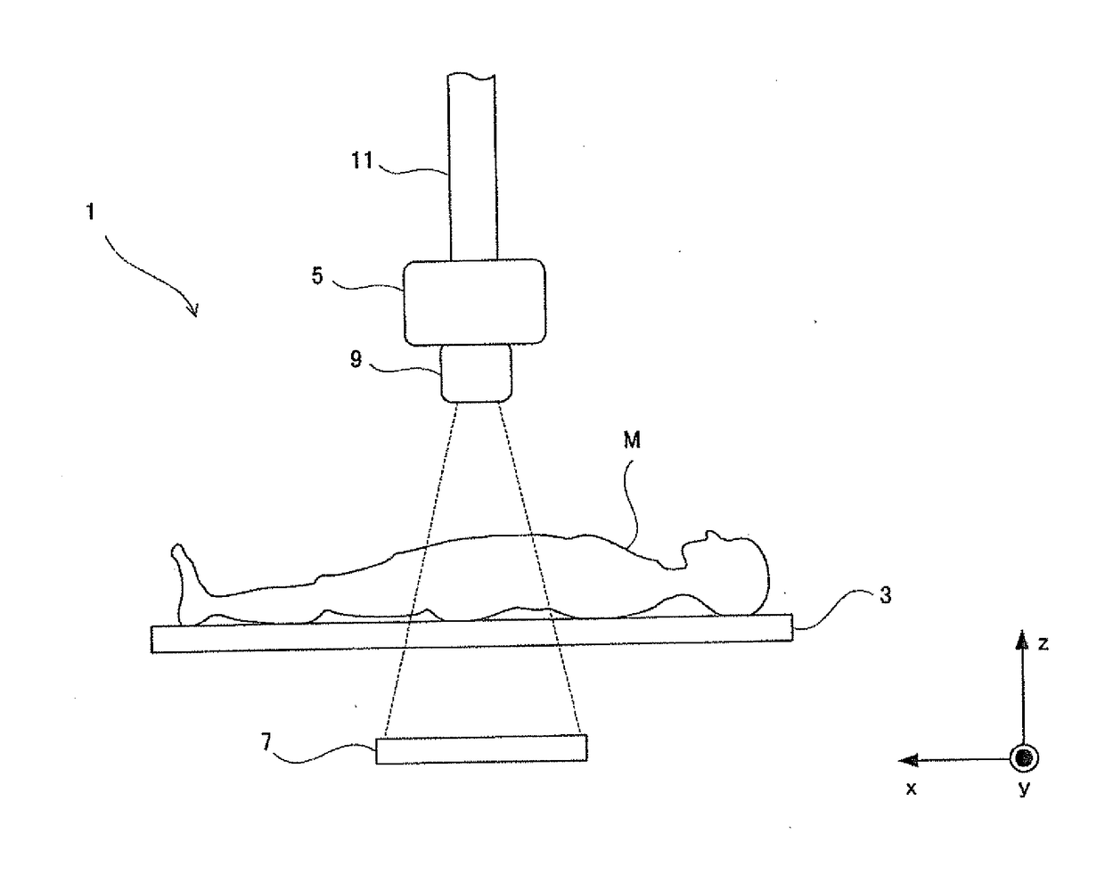
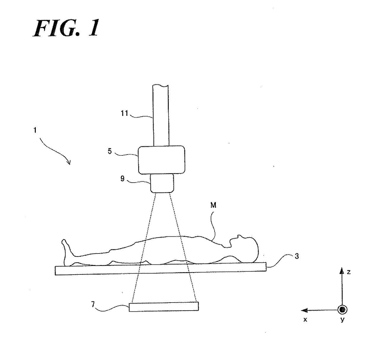
[0048]Referring to FIG. 1, an X-ray imaging apparatus 1 comprises a table 3, an X-ray tube 5, an X-ray detector 7, a collimator 9, and an image generation element 11. The subject M lies on the table 3 in a horizontal posture. The X-ray tube 5 irradiates the X-ray to the subject M. The X-ray tube 5 and the X-ray detector 7 are in-place facing each other sandwiching the table 3. The X-ray detector 7 detects the X-ray, irradiated to the subject M from the X-ray tube 5, that transmits through the subject M and converts to an electric signal therefrom and then outputs as a detection signal. A flat panel display (FPD) is used as the X-ray detector 7 according to the aspect of the Embodiment 1.

[0049]The collimator 9 is installed below the X-ray tube 5. The support post 11 having the base thereof on the ceiling of the examination room and hang-and-suppor...

embodiment 2

[0078]Next, referring to FIGs., the inventor sets forth the Embodiment 2 of the present invention. Further, an entire structure of the X-ray imaging apparatus according to the aspect of the Embodiment 2 and a flow-chart illustrating the operation steps is the same as for the X-ray imaging apparatus according to the aspect of the Embodiment 1. Accordingly, the inventor skips to set forth the detail while putting the same sign to respective components, the step of operations, but the inventor sets forth a mechanism characteristic relative to the Embodiment 2, in which the visible light control element 33 controls the visible light emitted from the visible light lamp 19.

Control of Visible Light According to the Embodiment 2

[0079]According to an X-ray imaging apparatus associated with the aspect of the Embodiment 1, the visible light source control element 33 controls blinking of the visible light irradiated from the visible light lamp 19 to the exposure field based on the data relative...


PUM


Abstract

An X-ray imaging apparatus comprises a distance detector 23, a distance calculation element 37 and a visible light source control element 33. The distance calculation element 37 calculates the distance from the visible light lamp 19 to the body surface of the subject based on the distance measured by the distance detector 23. The visible light source control element 33 controls a light intensity of a visible light emitted from the visible light source based on the calculated distance by the distance calculation element 37. The operator visually recognizes a brightness of the exposure field of the visual light, and can easily confirm that the visible light lamp has shifted to a suitable position for the X-ray imaging.

Description

CROSS REFERENCE TO RELATED APPLICATIONS[0001]This application relates to, but does not claim priority from, JP Ser. No. JP2014-074108 filed Mar.31, 2014, the entire contents of which are incorporated by reference.FIGURE SELECTED FOR PUBLICATION[0002]FIG. 3.BACKGROUND OF THE INVENTIONField of the Invention[0003]The present invention relates to an X-ray imaging apparatus that acquires an X-ray image of a subject by irradiating X-ray and particularly relates to the X-ray imaging apparatus having a collimator that limits the X-ray beam.Description of the Related Art[0004]In medical sites, the X-ray imaging apparatus that images the subject's X-ray image by irradiating X-ray to the subject is being applied. Referring to FIG. 9, a conventional X-ray imaging apparatus 101 comprises a table 103, an X-ray tube 105, an X-ray detector 107, a collimator 109, an image generation element 111 and a monitor 113.[0005]The subject M lies on the table 103 in a horizontal posture. The X-ray tube 105 ir...

Claims


Application Information

Patent Timeline
Patent Type & Authority Applications(United States)
IPC IPC(8): A61B6/00A61B6/06
CPCA61B6/06A61B6/542A61B6/587A61B6/588A61B6/589
Inventor KAWANO, MASAHIRO
Owner SHIMADZU CORP
Why Eureka
Try Eureka