Aerial Delivery Assembly

a technology for delivering assemblies and aircraft, which is applied in the direction of gliders, transportation and packaging, fuselages, etc., can solve the problems of many limitations, slow and/or dangerous delivery by land, and not always a viable option for delivery by land, so as to reduce the risk of damage, facilitate the process of reprogram, and mitigate or eliminate the error

Inactive Publication Date: 2018-03-29
COOK GEORGE MICHAEL
View PDF1 Cites 17 Cited by
  • Summary
  • Abstract
  • Description
  • Claims
  • Application Information

AI Technical Summary

Benefits of technology

[0047]In another embodiment, the control unit further comprises a communications unit adapted to receive a signal identifying the target location from an external communications unit. The communications module may be wired or wireless. In some embodiments, the communications module may be a short-range wireless communications module. In these embodiments, a user could easily reprogram the target location to which the goods are to be delivered. If a wireless communications unit is used, a user may be able to reprogram a number of the control units using a single command. In another embodiment, the communications unit can be a long-range wireless communications unit, which would allow the target location to be adjusted during flight, for example. This would be particularly advantageous where the goods were being delivered to a recipient that is mobile, for example, a person, as the destination could be adjusted. Examples of communications units include Bluetooth modules, infrared modules, USB connections and radio receivers and transmitters.
[0048]In another embodiment, the communications unit is further adapted to communicate with the communications unit of another assembly. In this embodiment, when more than one assembly is launched at a time, the assembly can share information and data between one another, particularly if they are all proceeding to the same target location. This data can be a signal providing any sensed data, such as current location, temperature, airspeed, altitude, local height, conditions or other information such as target location, updated instructions. For example, if the airspeed or positional sensors on an assembly are faulty or are inaccurate, any other assemblies that have been launched to the same target location can share information such as the

Problems solved by technology

While many systems for delivery of goods have been developed, many, however, have numerous limitations.
Often the intended delivery site is either in a very remote location or in a hostile region, which means that delivery by land, for example via a convoy of vehicles, can be slow and/or dangerous.
Furthermore, delivery by land is not always a viable option in regions where the terrain is impassable.
The alternative, delivery by air, is an expensive method of delivering goods and requires either a suitable landing zone for an aircraft or requires the use of aerial delivery systems, such as air drops, to deliver goods.
These limit the sites to which goods can be delivered and the aerial delivery methods are not always accurate.
In some hostile regions, even aerial delivery is too dangerous, as the risk to life and the aircraft is too high.
This is often costly and time consuming, as it will require flying to each site and landing/unloading.

Method used


Image

  • Aerial Delivery Assembly
  • Aerial Delivery Assembly
  • Aerial Delivery Assembly

Examples


first embodiment

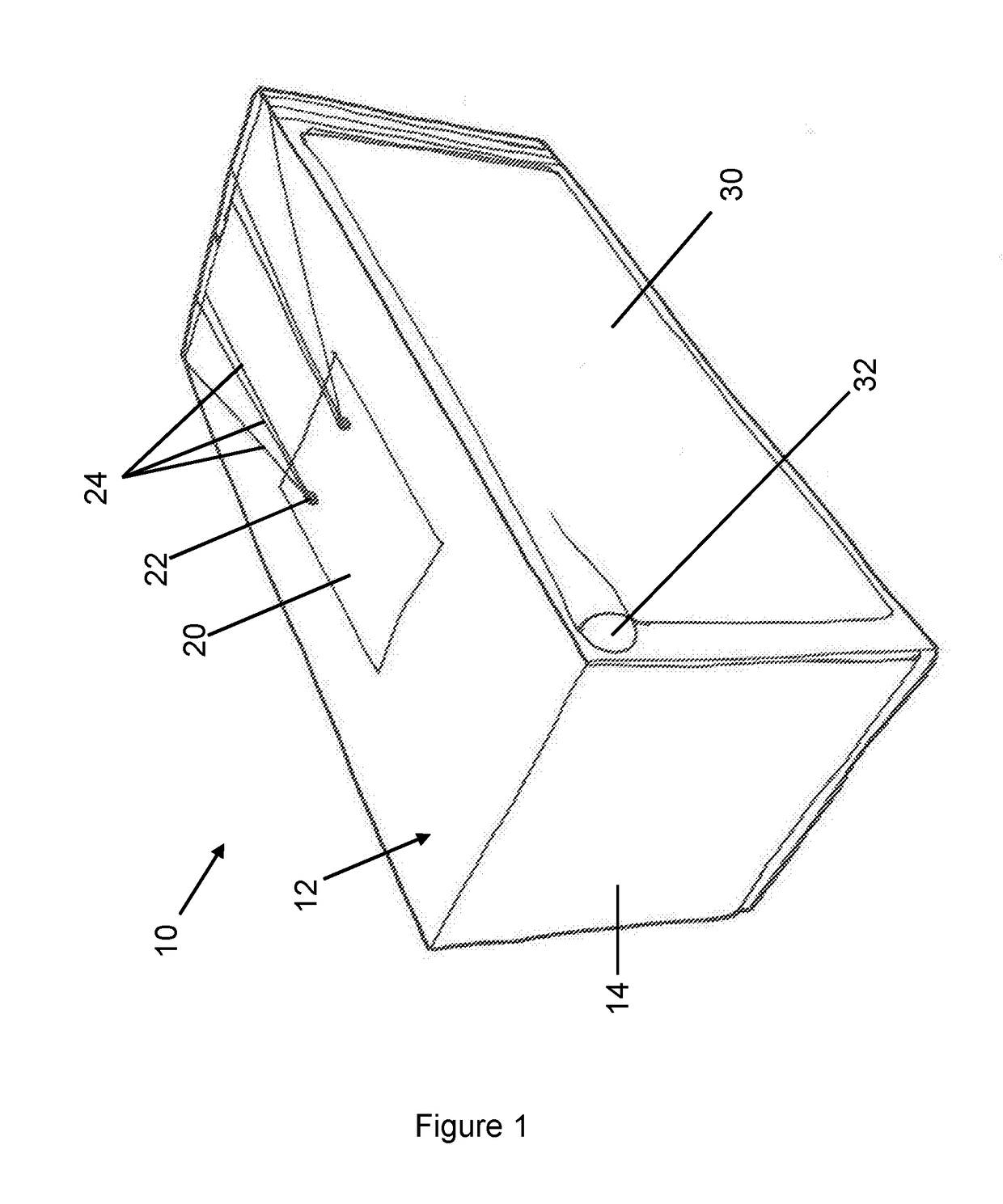
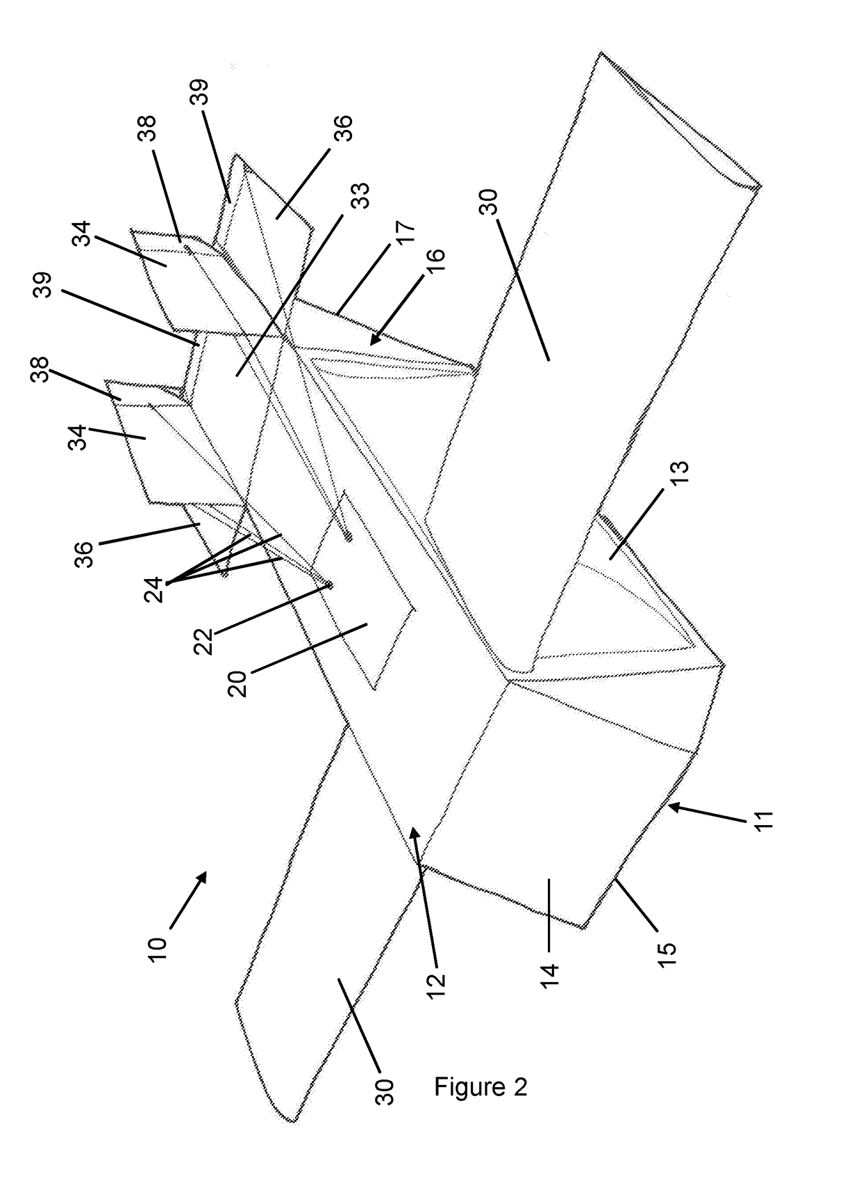
[0070]the invention is shown in FIGS. 1 and 2 in the form of a glider 10. FIGS. 1 and 2 depict the glider 10 in a collapsed (or stowed) configuration and a deployed configuration, respectively. The glider 10 acts as a means by which goods can be delivered to a target located easily and at a low cost, as will be explained below. The glider 10 is initially stored in the collapsed configuration shown in FIG. 1 so that it can be efficiently packed, or stacked together with other such gliders, for example. The size of the glider in the collapsed configuration shown in FIG. 1 is approximately 500 mm×500 mm×1200 mm. When the glider is launched, it automatically deploys (as will be discussed in detail, below) into the deployed configuration shown in FIG. 2 thus providing all of the required components to allow the efficient aerial delivery of the goods stored within the glider 10.

[0071]In this embodiment, the glider 10 comprises an airframe, the airframe being formed from corrugated cardboa...

third embodiment

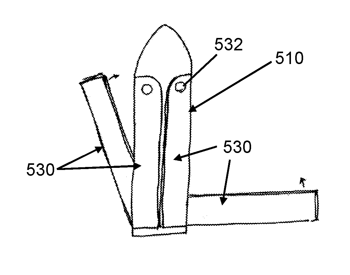
[0111]the invention is shown in FIGS. 6 and 7. The aircraft 210 of this embodiment has a similar basic structure to the previous embodiments in that it comprises a main body 212, wings 230a, 230b, a tail section 216, a hold for goods (not visible), a control unit and linkages. The main differences between this aircraft 210 and the gliders 10, 110 of the previous embodiments are the provision of propulsion means in the form of a deployable propeller 211, an internally mounted control unit (not visible), internally mounted linkages (not visible) and the wing 230a, 230b structure.

[0112]The control unit in this embodiment is housed within the main body 212 of the airframe so that it is not visible in normal use. It can be inserted into and removed from the main body via an access panel (not visible). Linkages extend from the control unit to the control surfaces and the wing deployment mechanisms internally, within the airframe. This reduces the risk of a linkage becoming snagged or dama...


PUM


Abstract

An aerial delivery assembly for autonomously delivering a load to a target location, the assembly comprising an airframe which comprises a main body, at least one deployable lift providing structure, the lift providing structure being moveable between a stowed position and a deployed position; and at least one deployable and adjustable control structure for controlling the flight of the assembly and moveable between a stowed position and a deployed position. The main body comprises a compartment for receiving a load to be delivered. The assembly further comprises a control unit comprising an actuation module for use in adjusting the control structure, wherein the control unit is releaseably connected to the airframe such that it is reusable in an aerial delivery assembly having a different airframe.

Description

FIELD OF INVENTION[0001]The present invention relates to an aerial delivery assembly, in particular an aircraft for the autonomous aerial delivery of a load to a target location.BACKGROUND TO THE INVENTION[0002]Logistics is a fundamental part of any operation, whether a humanitarian, commercial or military operation and vast sums of money are spent building infrastructure and delivering goods to remote or hard-to-reach locations. While many systems for delivery of goods have been developed, many, however, have numerous limitations.[0003]Often the intended delivery site is either in a very remote location or in a hostile region, which means that delivery by land, for example via a convoy of vehicles, can be slow and / or dangerous. Furthermore, delivery by land is not always a viable option in regions where the terrain is impassable. The alternative, delivery by air, is an expensive method of delivering goods and requires either a suitable landing zone for an aircraft or requires the u...

Claims


Application Information

Patent Timeline
IPC IPC(8): B64C39/02B64C13/30
CPCB64C39/024B64C13/30B64C2201/021B64C2201/102B64C2201/128B64C2201/141B64C2211/00B64U30/12B64U2101/60B64C13/28Y02T50/40B64U10/25B64U2201/10B64C1/061B64C3/56B64C31/02B64C2001/0054
Inventor COOK, GEORGE MICHAELCOOK, JONATHAN EDWARDCOOK, MICHAEL KEVIN
Owner COOK GEORGE MICHAEL
Why Eureka
Try Eureka