Tensioner
a technology of tensioner and tensioner plate, which is applied in the direction of belt/chain/gearing, mechanical equipment, belt/chain/gearing, etc., can solve the problems of transmission chain vibration and transmission chain damage, and achieve satisfactory damping effect, increase the capacity of oil storage chamber, and improve the stability of the installation state of the check valv
- Summary
- Abstract
- Description
- Claims
- Application Information
AI Technical Summary
Benefits of technology
Problems solved by technology
Method used
Image
Examples
first embodiment
[0027]A tensioner 10 according to the present invention will be described hereinbelow with reference to the figures.
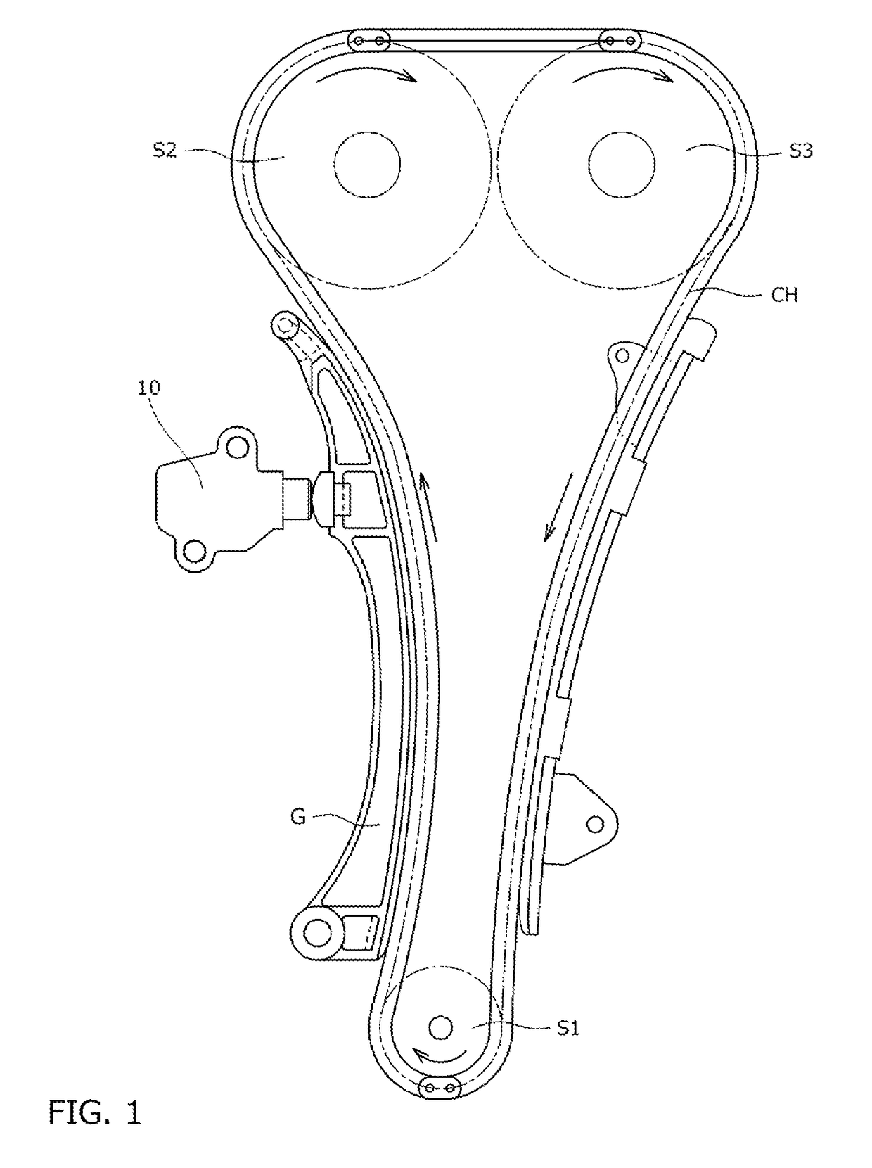
[0028]First, as shown in FIG. 1, a tensioner 10 is incorporated in a chain transmission device used, for example, for a timing system of an automobile engine, and is attached to an engine block (not shown in the figure). The tensioner applies, through a tensioner lever G, appropriate tension to the slack side of a transmission chain CH wound, on a plurality of sprockets S1 to S3, thereby suppressing vibrations occurring when the automobile travels.
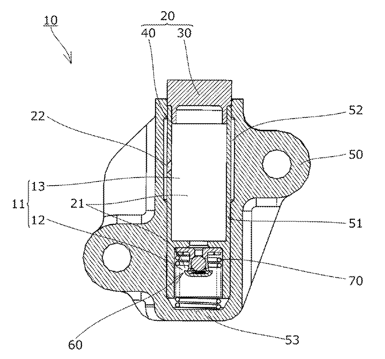
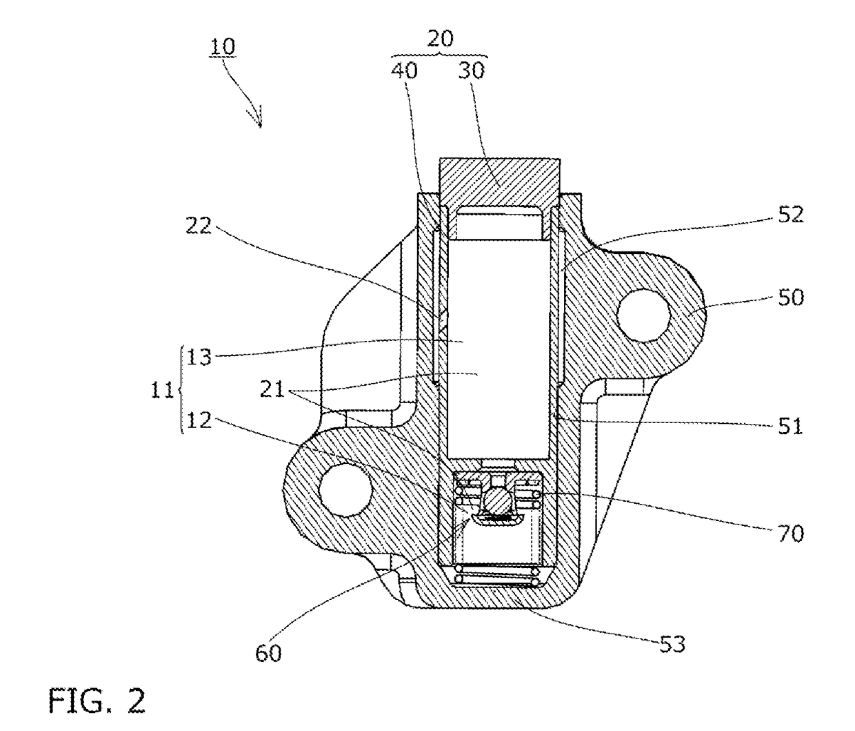
[0029]As shown in FIG. 2, the tensioner 10 includes a plunger 20 having a plunger hole 21 opened to the rear side, a housing 50 having a plunger accommodating hole 51 opened to the front side and accommodating the plunger 20, a check valve 60 that allows oil to flow from an oil storage chamber 13 on the front side, which is formed in an internal space 11 between the housing 50 and the plunger 20, into a pressure oil chamber 1...
second embodiment
[0044]In the second embodiment, as shown in FIG. 5, the front-side plunger part 30 has the pressing front end portion 31, the front-side sliding cylindrical portion 32 which is formed so as to protrude from the rear surface of the pressing front end portion 31 toward the rear side and is slidably disposed on the inner peripheral surface of the plunger accommodating hole 51, and an annular fitting protruding portion 33 formed to protrude from the rear surface of the front-side sliding cylindrical portion 32 toward the rear side.
[0045]Further, in the second embodiment, the plunger through hole 22 passing through from the outer peripheral side to the inner peripheral side is formed in the front-side sliding cylindrical portion 32.
[0046]Further, as shown in FIG. 5, the outer peripheral surfaces of the pressing front end portion 31 and the front-side sliding cylindrical portion 32 are formed flush with the outer peripheral surface of the rear-side sliding cylindrical portion 41. The oute...
third embodiment
[0049]First, in the third embodiment, as shown in FIG. 6, the fitting protruding portion 33 is not formed at. the front-side plunger part 30.
[0050]Further, the first cylindrical portion 41a is not formed at the rear-side sliding cylindrical portion 41 of the rear-side plunger part 40, and an annular fitting protruding portion 43 formed to protrude from the front surface of the rear-side sliding cylindrical portion 41 toward the front side is formed at the rear-side plunger part 40.
[0051]Further, as shown in FIG. 6, the cater peripheral surfaces of the pressing front end portion 31 and the front-side sliding cylindrical portion 32 are formed flush with the outer peripheral surface of the rear-side sliding cylindrical portion 41. The outer diameter dimensions of the pressing front end portion 31, the front-side sliding cylindrical portion 32, and the rear-side sliding cylindrical portion 41 may be set so that the outer peripheral surfaces of the pressing front end portion 31 and the f...
PUM
 Abstract
Description
Claims
Application Information
 - R&D
- Intellectual Property
- Life Sciences
- Materials
- Tech Scout
- Unparalleled Data Quality
- Higher Quality Content
- 60% Fewer Hallucinations
Browse by: Latest US Patents, China's latest patents, Technical Efficacy Thesaurus, Application Domain, Technology Topic, Popular Technical Reports.
© 2025 PatSnap. All rights reserved.Legal|Privacy policy|Modern Slavery Act Transparency Statement|Sitemap|About US| Contact US: help@patsnap.com


