Lubrication system and a method for controlling the lubrication system

a lubrication system and lubrication system technology, applied in the direction of gear lubrication/cooling, toothed gearings, gearings, etc., can solve the problems of reducing the rolling the roll loss of the roller bearing, so as to reduce the power loss of the gearbox

Active Publication Date: 2018-03-29
SCANIA CV AB
View PDF0 Cites 2 Cited by
  • Summary
  • Abstract
  • Description
  • Claims
  • Application Information

AI Technical Summary

Benefits of technology

[0006]The object of the present invention is to provide a lubrication system providing a required lubrication and cooling of including components in a gearbox at the same time as it is possible to reduce power losses in the gearbox.

Problems solved by technology

A too large oil flow to a roller bearing results in rolling losses.
Unnecessarily large oil flows to the roller bearing is prevented resulting in lower rolling losses in the roller bearings.

Method used


Image

  • Lubrication system and a method for controlling the lubrication system
  • Lubrication system and a method for controlling the lubrication system
  • Lubrication system and a method for controlling the lubrication system

Examples


Embodiment Construction

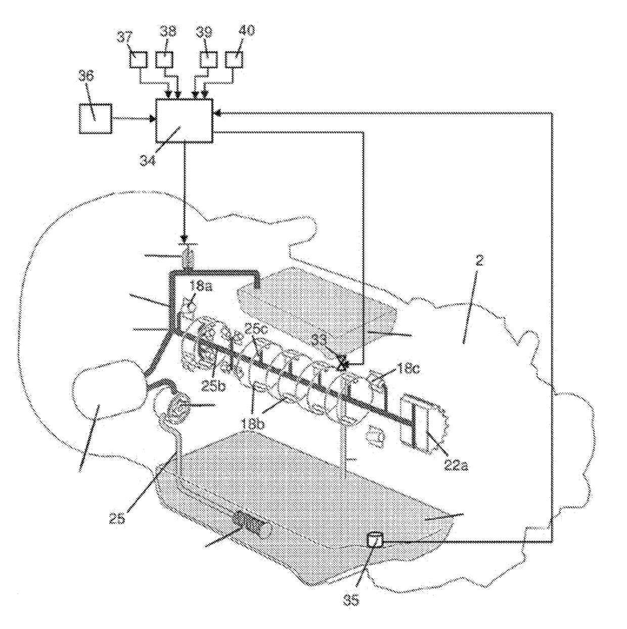
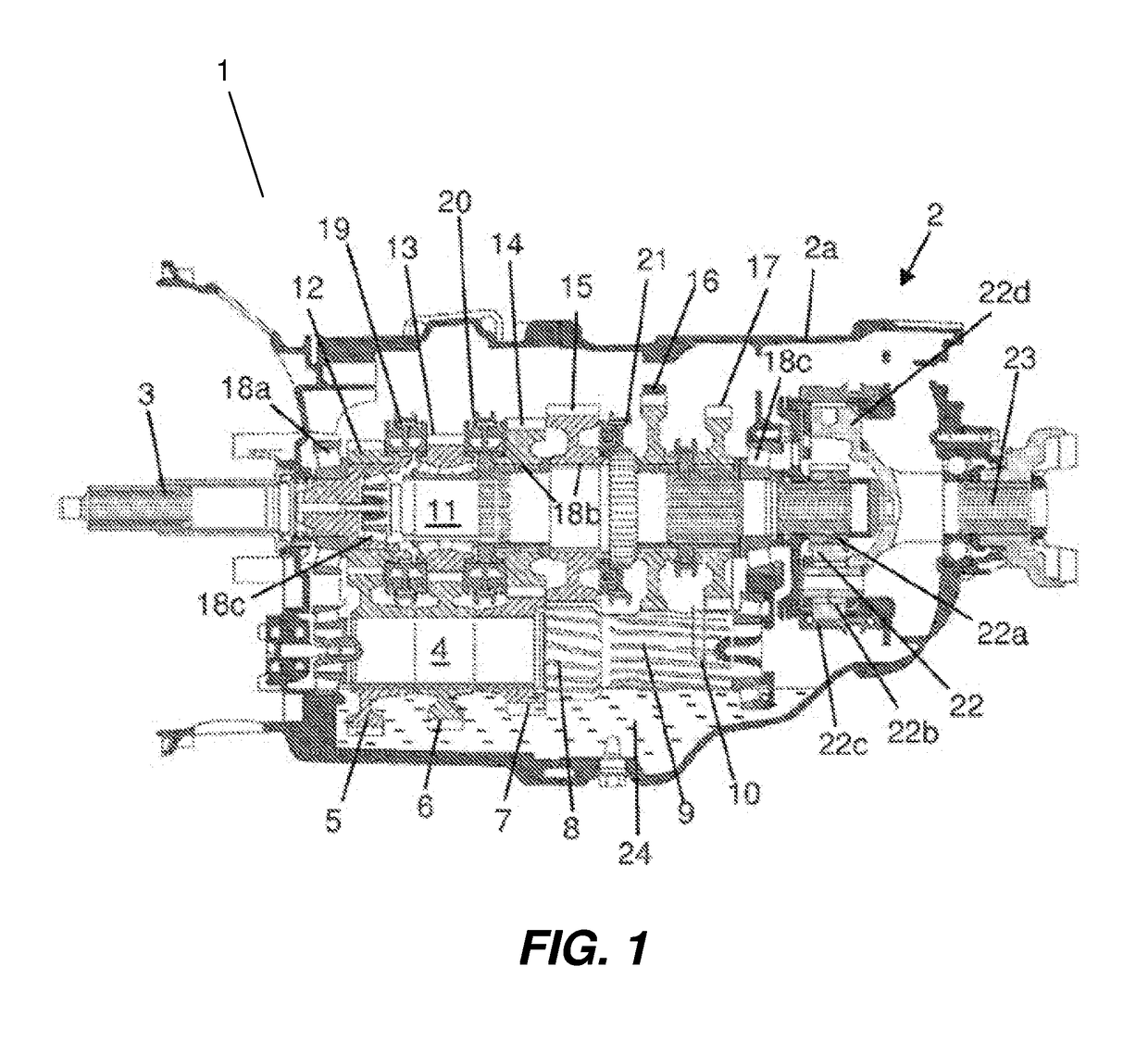
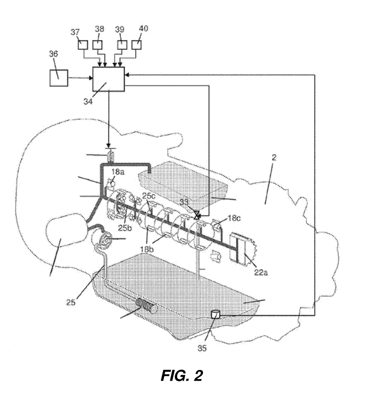
[0021]FIG. 1 shows a gearbox 2 arranged in a schematically indicated vehicle 1. The vehicle 1 may be a heavy vehicle. The gearbox 2 comprises a housing 2a and an input shaft 3 driven by a not shown combustion engine. The gearbox comprises further a counter shaft 4 provided with a plurality of gearwheels 5-10 of different sizes. In this case, the gearwheels 5-10 are fixedly arranged on the counter shaft 4. The gearbox 2 comprises a main shaft 11 provided with a plurality of gearwheels 12-17 of different sizes. Each gearwheel on 5-10 the counter shaft 4 is in constant engagement with a gearwheel 12-17 on the main shaft 11 such that they form a number of gearwheel pairs in the gearbox 2. Each gearwheel pair includes a primary gearwheel 5-10 fixedly arranged on the counter shaft 4 and secondary gear wheel 12-17 rotatably arranged on the main shaft 11 or the input shaft 3.

[0022]The gearbox 2 is equipped with a split gear which in a first split position connects the input shaft 3 with the...


PUM


Abstract

The invention relates to a lubrication system and method for controlling the lubrication system. The lubrication system comprises a bypass line by which it is possible to lead a part of the oil flow in the oil line past a component to be lubricated and back to the oil sump, a first valve configured to regulate the oil flow through the bypass line and a control unit. The control unit is configured to receive information from at least one parameter related to the oil flow to said component to estimate a required oil flow to said component in view of said parameter and to regulate the first valve such that a part of the oil flow in the oil line is led to the bypass line and that a remaining part of the oil flow, which corresponds to the required oil flow, is led to said component.

Description

BACKGROUND OF THE INVENTION AND PRIOR ART[0001]The present invention relates to a lubrication system and a method for controlling the lubrication system according to the preamble of claims 1 and 11.[0002]Conventional gearboxes comprise a main shaft, a counter shaft, a plurality of gearwheel pairs each comprising a primary gearwheel arranged on the counter shaft and a secondary gearwheel rotatably arranged on the main shaft by means of roller bearings. The primary gearwheel and the secondary gearwheel of the respective gearwheel pairs are continuously in meshing engagement with each other. The primary gearwheels on the counter shaft are positioned at a lower level than the secondary gearwheels on the main shaft. The gearbox comprises an oil sump at a bottom portion. The oil sump is filled with gearbox oil up to a level such that substantially all primary gearwheels are continuously in contact with the oil in the oil sump. During operation, the primary gearwheel of the respective gear...

Claims


Application Information

Patent Timeline
Patent Type & Authority Applications(United States)
IPC IPC(8): F16H57/04F16H3/091
CPCF16H57/0435F16H57/0449F16H57/0471F16H57/043F16H3/091F16H57/0494F16H57/042F16H57/0436F16H57/0409F16H57/0431F16H57/0441F16H57/0447F16H57/045F16H57/0452F16H57/0456F16H57/0484F16H57/0434
Inventor ARNELOF, PERFORSBERG, JORGEN
Owner SCANIA CV AB
Why Eureka
Try Eureka