
Functional Roof Construction Method and Arrangement

a roof and functional technology, applied in the field of roof structures, can solve the problems of difficult repair time-consuming, poor heat insulation of conventional roof structures, etc., and achieve the effects of enhancing practical use, reducing installation costs, and being convenient to us

Inactive Publication Date: 2018-04-05
WU SHIH HSIANG +2
View PDF0 Cites 32 Cited by
  • Summary
  • Abstract
  • Description
  • Claims
  • Application Information

AI Technical Summary

Benefits of technology

The present invention is a functional roof construction method and arrangement that allows for the installation of different functional panels at different levels for multiple functions. The functional panels can be locked in place to retain their position and easily assembled together to form a rigid roof structure. The invention also allows for the collection and re-cycling of water, easy repair and maintenance of the functional roof modules, and the incorporation of additional functions such as internet router, rechargeable battery, communication device, and security system. Overall, this invention enhances the practical use of the roof construction while reducing installation cost and maintenance cost.

Problems solved by technology

In other words, the conventional roof structure provides poor heat insulation.
In addition, the conventional roof structure has several drawbacks.
The conventional roof structure is hard to repair especially when a portion thereof is damaged.
It is time consuming and is a waste of material since the roof materials cannot be re-used.
The repairing cost of the damaged roof structure is relatively high to include the labor cost of the constructers.
In addition, the conventional roof structure has a limited service lifespan depending on the material thereof In other words, the life expectancy of the roof varies between different roof materials.
Even though many roof designs are found to improve the roof materials and / or the efficiency of the roof, the basic frame structure of the roof has not be changed.
However, the above existing problems cannot be solved.
However, the solar panels are costly and required licensed roof contractors to install.
Therefore, the rooftop solar system may not be able to install on the old roof structure.
In addition, the installation of the rooftop solar system requires drilling on the roof structure, such that the existing roof structure will be damaged.

Method used


Image

  • Functional Roof Construction Method and Arrangement
  • Functional Roof Construction Method and Arrangement
  • Functional Roof Construction Method and Arrangement

Examples


Embodiment Construction

[0045]The following description is disclosed to enable any person skilled in the art to make and use the present invention. Preferred embodiments are provided in the following description only as examples and modifications will be apparent to those skilled in the art. The general principles defined in the following description would be applied to other embodiments, alternatives, modifications, equivalents, and applications without departing from the spirit and scope of the present invention.

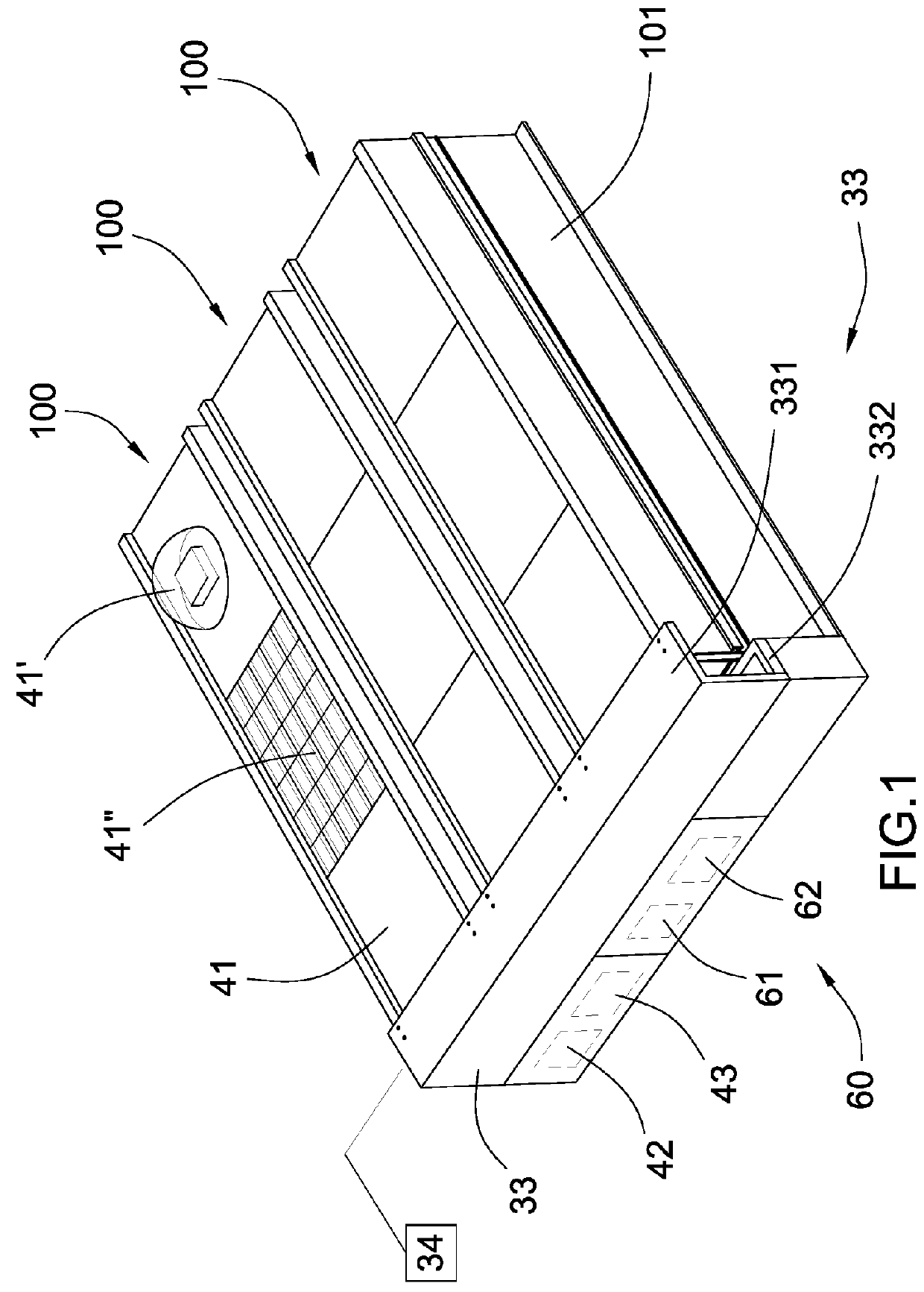
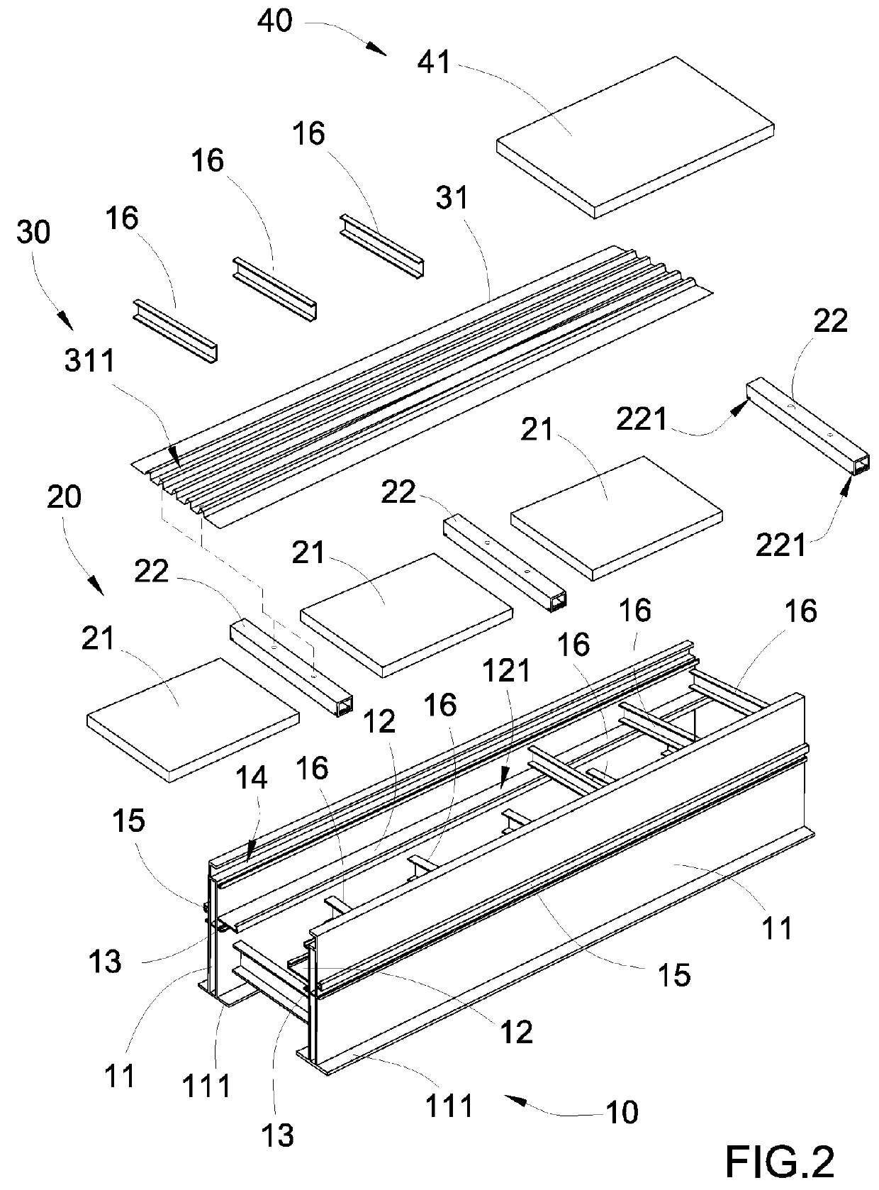
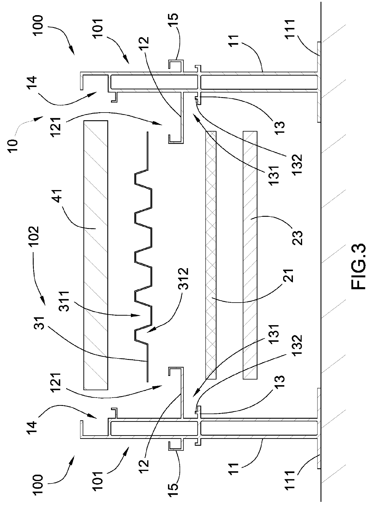
[0046]Referring to FIGS. 1 to 5 of the drawings, a functional roof construction arrangement according to a preferred embodiment of the present invention is illustrated, wherein the functional roof construction arrangement of the present invention is arranged for mounting on a roof frame of a building to replace the existing roof structure, as shown in FIG. 6. In particular, the roof frame of the building has a predetermined pitch to define a slope that the roof frame is constructed to have an inc...


PUM


Abstract

A functional roof construction arrangement for a roof frame of a building, includes a plurality of functional roof modules being assembled together. Each of the functional roof modules includes a module housing and a roof functional unit which includes three different roof functional panel units selectively supported by the module housing at different levels thereof to provide different functions for the building. The roof functional panel units are selectively configured for selectively providing multiple functions of solar energy collection, thermal insulation, sound insulation, wireless network system, and the like.

Description

CROSS REFERENCE OF RELATED APPLICATION[0001]This is a Continuation-In-Part application that claims the benefit of priority under 35 U.S.C.§ 120 to a non-provisional application, U.S. application Ser. No. 15 / 093,728, filed Apr. 7, 2016.NOTICE OF COPYRIGHT[0002]A portion of the disclosure of this patent document contains material which is subject to copyright protection. The copyright owner has no objection to any reproduction by anyone of the patent disclosure, as it appears in the United States Patent and Trademark Office patent files or records, but otherwise reserves all copyright rights whatsoever.BACKGROUND OF THE PRESENT INVENTIONField of Invention[0003]The present invention relates to a roof structure, and more particularly to a functional roof construction method and arrangement, wherein a plurality of functional roof modules are assembled to form a rigid roof structure for selectively providing multiple functions of solar energy collection, thermal insulation, sound insulati...

Claims


Application Information

Patent Timeline
Patent Type & Authority Applications(United States)
IPC IPC(8): E04D3/18E04D3/24E04D3/36E04D13/16H02S20/23H02S30/10H02S40/12
CPCE04D3/18E04D3/24E04D3/36E04D13/1693H02S20/23H02S30/10H02S40/12E04D3/30E04D3/366E04D2013/045F24S20/67F24S25/33F24S25/35F24S40/44F24S2025/014F24S2025/801H02S20/25H02S40/44Y02B10/10Y02B10/20Y02B10/70Y02E10/47Y02E10/50Y02E10/60H02S20/24
Inventor WU, SHIH HSIANGWU, CHENG LINWU, CHIA I
Owner WU SHIH HSIANG
Learn More