Intake and exhaust system of internal combustion engine

a technology of internal combustion engine and exhaust system, which is applied in the direction of engines, mechanical equipment, machines/engines, etc., can solve the problems of insufficient cooling of egr gas entering the second evaporator, insufficient thermal energy obtained in the first evaporator, and insufficient cooling of egr gas passing through the second evaporator, etc., to achieve simple and economical way of system structure construction

Active Publication Date: 2018-04-05
HONDA MOTOR CO LTD
View PDF4 Cites 4 Cited by
  • Summary
  • Abstract
  • Description
  • Claims
  • Application Information

AI Technical Summary

Benefits of technology

[0018]By using the radiator for cooling the cooling water of the internal combustion engine for cooling the cooling water for the condenser, the system structure can be constructed in a both simple and economical way.
[0019]Thus, the present invention provides an intake and exhaust system of an internal combustion engine provided with an EGR device that allows an adequate amount of thermal energy to be obtained in an evaporator, and the exhaust gas to be cooled and recirculated so that the EGR gas may be further cooled by using the thermal energy obtained in the evaporator.

Problems solved by technology

When the EGR gas is cooled by an EGR cooler using the atmospheric air as the cooling medium, the EGR gas may not be adequately cooled when the temperature of the available air is excessively high.
Since the water droplets are harmful to the turbocharger of the internal combustion engine, it is necessary to cool the EGR gas to a temperature level lower than that of the intake air before mixing the EGR gas with the intake air.
In this cooling circuit, since the EGR gas does not pass through the first evaporator, and flows directly into the second evaporator while still in a high temperature condition, there is a possibility that the EGR gas may not be sufficiently cooled when introduced into the second evaporator.
In this cooling circuit, since the gas passing through the first evaporator consists solely of the EGR gas, the thermal energy obtained in the first evaporator may not be sufficient for cooling the EGR gas passing through the second evaporator.

Method used


Image

  • Intake and exhaust system of internal combustion engine
  • Intake and exhaust system of internal combustion engine

Examples


Embodiment Construction

)

[0022]An embodiment of the present invention is described in the following with reference to appended drawings.

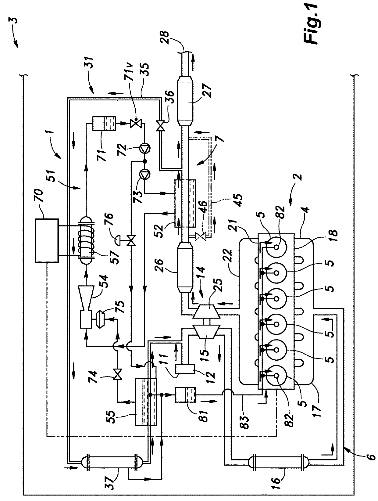
[0023]As shown in FIG. 1, an internal combustion engine 2 incorporated with an intake and exhaust system 1 embodying the present invention is mounted on a vehicle. The intake and exhaust system 1 is connected to a main body 4 of the internal combustion engine 2, and is provided with an intake passage 6 and an exhaust passage 7 communicating with cylinders 5 provided in the engine main body 4.

[0024]The intake passage 6 extends from an intake inlet 11 to an intake manifold 17 connected to the intake side of the engine main body 4 via an air cleaner 12, a compressor 15 of a turbocharger 14, and an intercooler 16 for cooling the intake air, in that order. The intake passage 6 branches off in the intake manifold 17, and communicates with intake ports 18 of the respective cylinders 5. In the following description of the intake system of the internal combustion engine 2, the term...


PUM


Abstract

An intake and exhaust system of an internal combustion engine includes an exhaust gas recirculation passage (35) communicates a part of an exhaust passage (7) downstream of a turbine with a part of an intake passage (6) upstream of a compressor and a cooling circuit (51), the cooling circuit including a first evaporator (52) provided in a part of the exhaust passage downstream of the turbine and upstream of a junction with the exhaust gas recirculation passage and storing a medium, an ejector pump (54) using vapor from the first evaporator as a driving flow, a condenser (57) for cooling and condensing the vapor ejected from the ejector pump and returning the condensed medium to the first evaporator, and a second evaporator (55) provided in the exhaust gas recirculation passage to cool the exhaust gas passing through the exhaust gas recirculation passage by evaporating a medium stored therein with a negative pressure created by the ejector pump.

Description

TECHNICAL FIELD[0001]The present invention relates to an intake and exhaust system of an internal combustion engine, and in particular to an intake and exhaust system including a cooling circuit in which exhaust gas is recirculated in an exhaust recirculation device.BACKGROUND ART[0002]As a method for suppressing knocking of an internal combustion engine, it is know to use an EGR (exhaust gas recirculation) device that mixes a part of the exhaust gas of an internal combustion engine with intake air as EGR gas, and forwards the mixture to the intake system of the internal combustion engine. Since knocking diminishes as the temperature of the gas fed to the intake system decreases, it is desirable to lower the temperature of the gas fed to the intake system as much as possible. Since the exhaust gas of the internal combustion engine is high in temperature, the EGR apparatus for performing such an EGR operation is often provided with an EGR cooler for cooling the exhaust gas.[0003]When...

Claims


Application Information

Patent Timeline
Patent Type & Authority Applications(United States)
IPC IPC(8): F02B47/10F02B29/04F01P3/22F02M26/05F02M26/24
CPCF02B47/10F02B29/0443F01P3/22F02M26/05F02M26/24F02B29/0475F02M26/30F02M26/19F02M26/23F02M26/29F01P2060/02F01P2060/16F02B47/02F02B47/08F02M26/06Y02T10/12
Inventor TAKAHASHI, NOBU
Owner HONDA MOTOR CO LTD
Why Eureka
Try Eureka