Charging system for electrically driven vehicles

Active Publication Date: 2018-04-12
TOYOTA JIDOSHA KK
View PDF2 Cites 3 Cited by
  • Summary
  • Abstract
  • Description
  • Claims
  • Application Information

AI Technical Summary

Benefits of technology

[0020]With the aspect, the electric vehicle can have precedence over the hybrid vehicle and can use the time zone in which the hybrid vehicle is limited in using the electricity supply equipment. As a result, it is possible to effectively u

Problems solved by technology

In the future, when electrically driven vehicles that can perform external charging are widely used, it is doubtful whether or not a limited number of public charging stations can cover the charging-needs of all of the electrically driven vehicles.
In addition, even if a sufficient number of charging stations are built, practical difficulties are postulated in establishing a large-scale electricity network in which all of the electrically driven vehicles can simultaneously perform external charging.
Even though external charging cannot be performed, the hybrid vehicle can travel or generate electricity by using the internal combustion engine when fuel is supplied to the internal combustion engine.
In contrast, since the electric vehicle is provided with no internal combustion engine, when external charging cannot be performed and an electricity storage device storing electricity to be supplied to the motor becomes empty, the electric vehicle cannot travel any long

Method used


Image

  • Charging system for electrically driven vehicles
  • Charging system for electrically driven vehicles
  • Charging system for electrically driven vehicles

Examples


embodiment 1

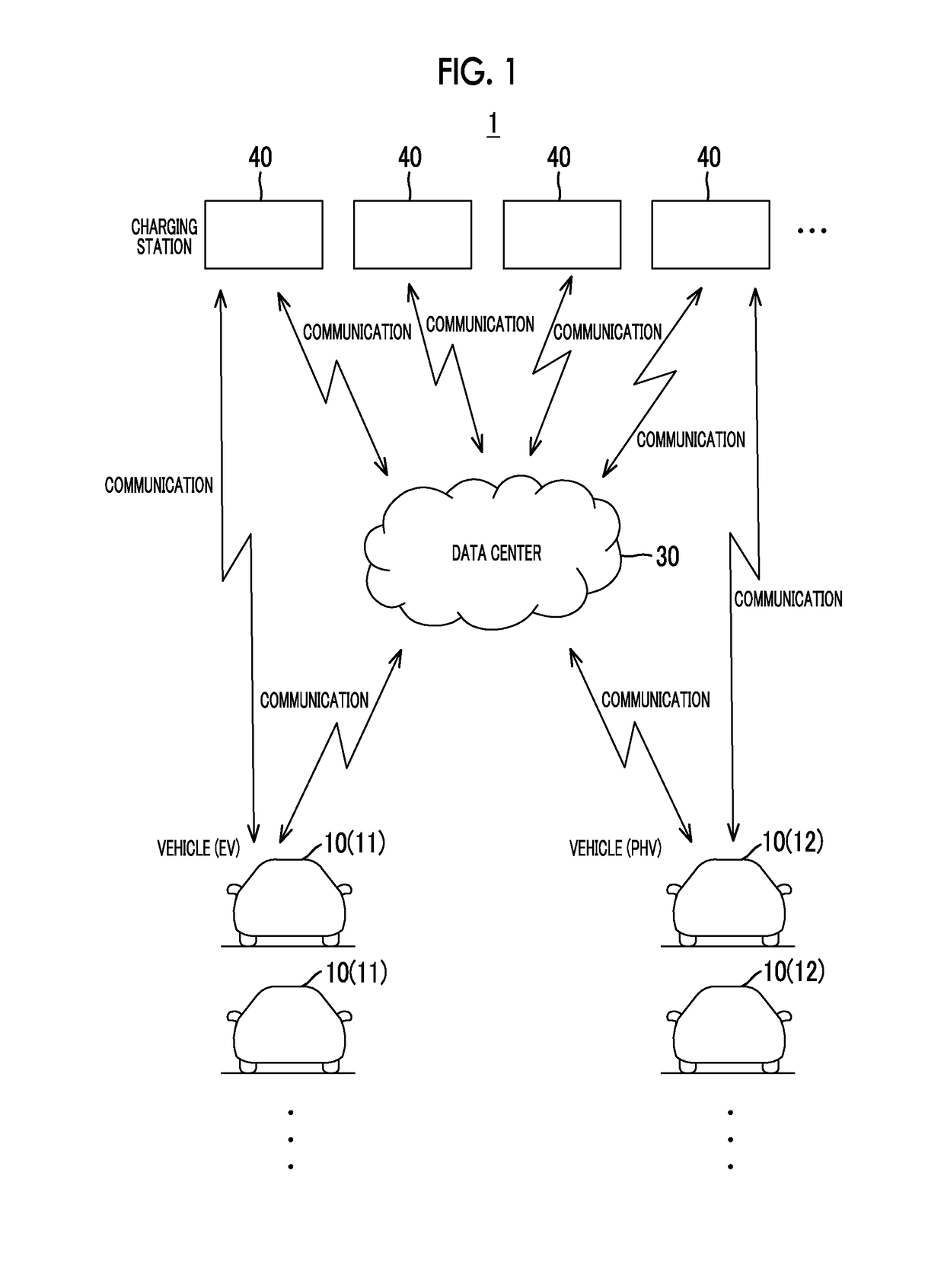
[0033]FIG. 1 is a view schematically illustrating an example of an overall configuration of a charging system 1 according to an embodiment. The charging system 1 includes a plurality of vehicles 10, a data center 30, and a plurality of charging stations 40.

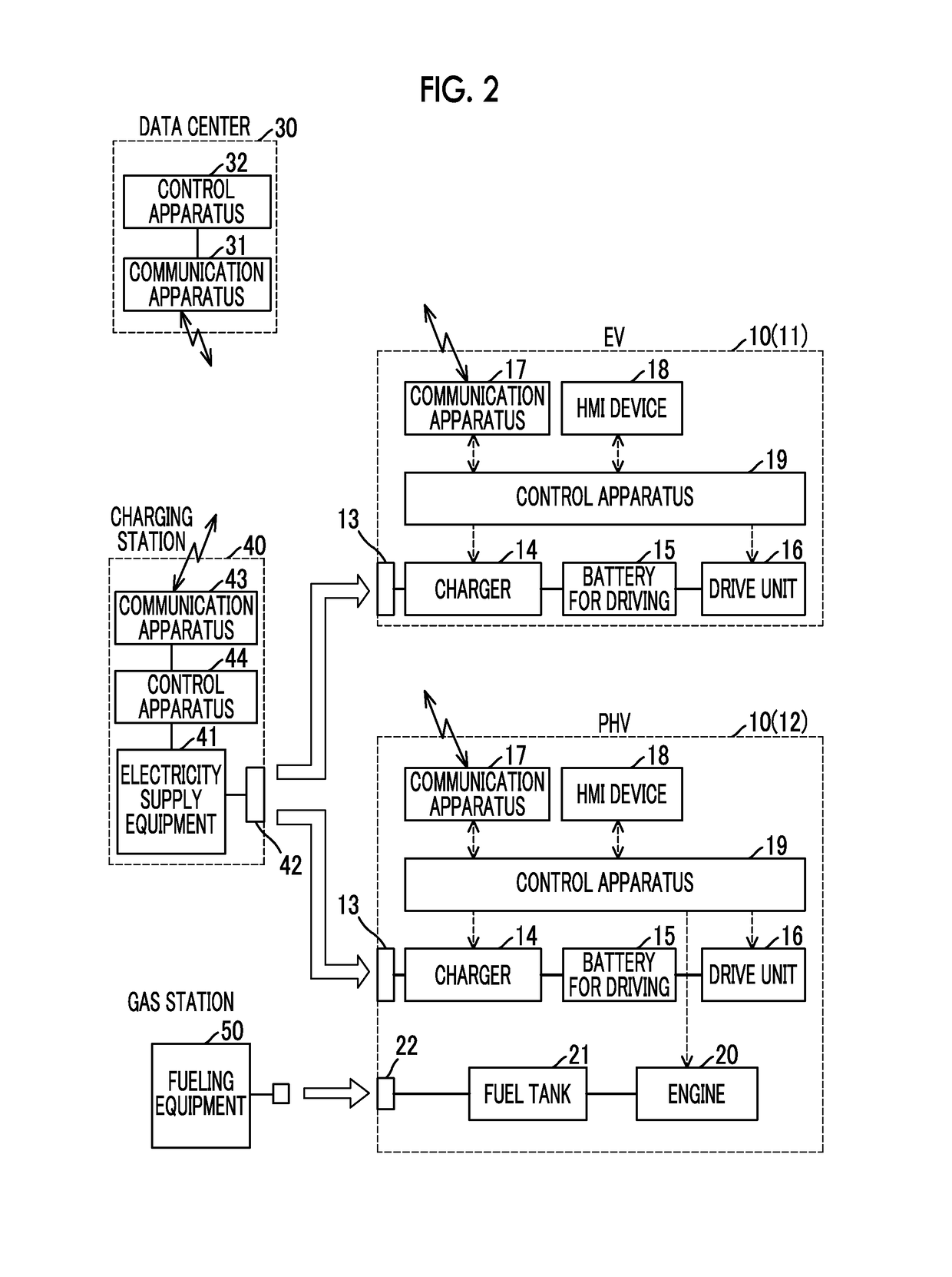
[0034]Each of the vehicles 10 is an electrically driven vehicle configured to be able to perform external charging. The vehicles 10 include an electric vehicle (hereinafter, will be also referred to as “EV”) 11 and a plug-in hybrid vehicle (hereinafter, will be also referred to as “PHV”) 12. The electric vehicle 11 is provided with a motor generator and provided with no engine. The plug-in hybrid vehicle 12 is provided with a motor generator and an engine.

[0035]Each of the charging stations 40 is a public facility that is provided with at least one set of electricity supply equipment for performing external charging for the vehicle 10 and can be used by an unspecified large number of users. Each of the charging stations 40 is conf...

modification example 1

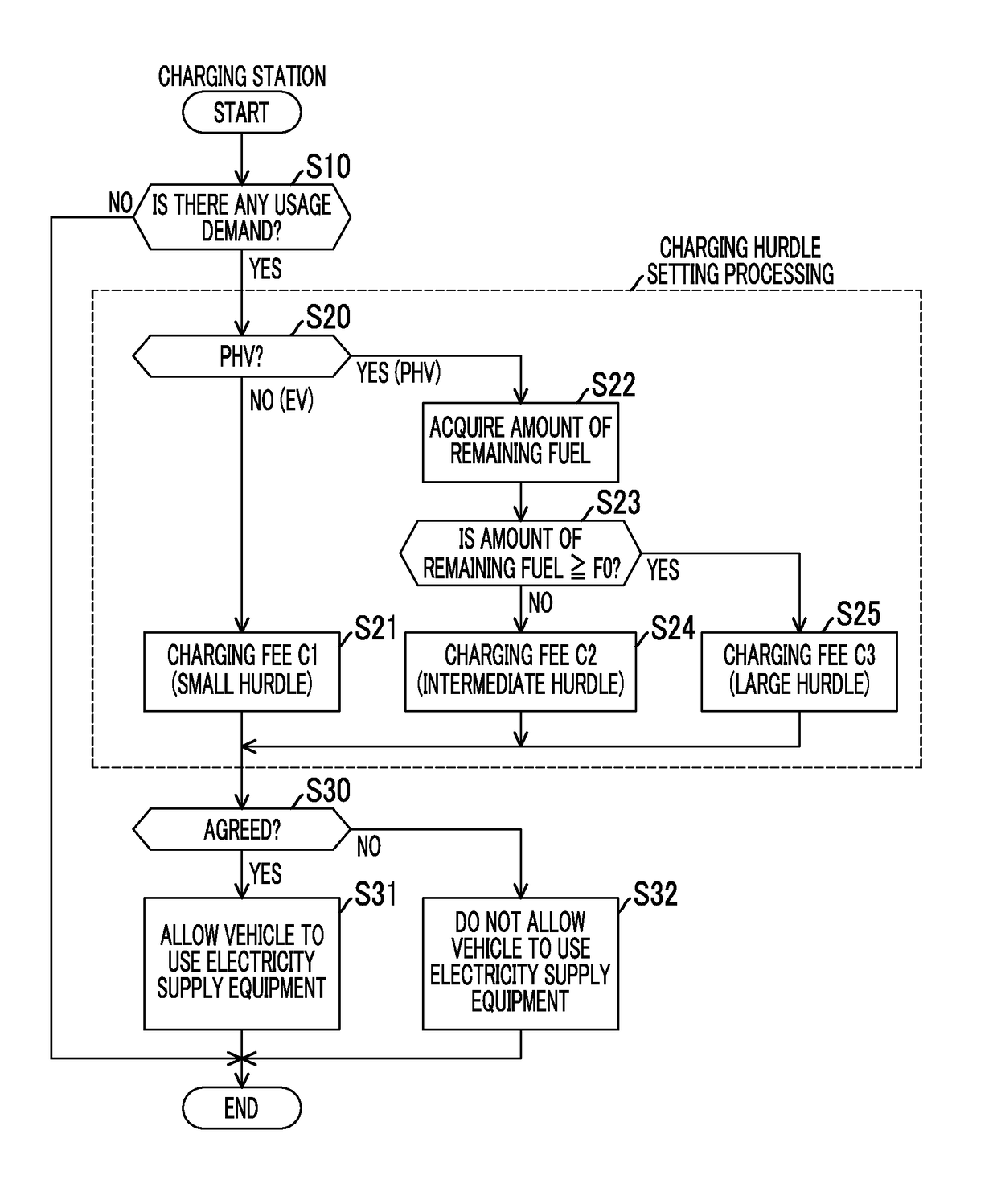
[0075]In the charging hurdle setting processing according to Embodiment 1, the usage condition (charging fee) is set based on parameters such as the type of the usage demand vehicle (whether the vehicle is the PHV 12 or the EV 11) and the amount of remaining fuel of the PHV 12.

[0076]However, the parameter used in setting the usage condition is not limited to the above-described parameters. For example, the usage condition may be set based on parameters such as the type of the usage demand vehicle, a SOC indicating the state of charge of the battery 15 for driving, and the type of the electricity supply equipment 41 (whether the electricity supply equipment is the DC electricity supply equipment or the AC electricity supply equipment).

[0077]FIG. 5 is a view illustrating a different example of the charging fee set through the charging hurdle setting processing according to Modification Example 1. In FIG. 5, the horizontal axis indicates the SOC of the battery 15 for driving, and the v...

modification example 2

[0082]In Embodiment 1, descriptions are given regarding an example in which the control apparatus 44 of the charging station 40 executes the entire processing illustrated in the flowchart in FIG. 3. However, all or a part of the processing illustrated in the flowchart in FIG. 3 may be executed by the control apparatus 32 of the data center 30 while the control apparatus 32 of the data center 30 communicates with the charging station 40 and the vehicle 10.


PUM


Abstract

A control apparatus of a charging system for electrically driven vehicles sets a first usage condition for a hybrid vehicle when an electrically driven vehicle fusing electricity supply equipment is the hybrid vehicle provided with an internal combustion engine, and set a second usage condition for an electric vehicle different from the first usage condition when an electrically driven vehicle using the electricity supply equipment is the electric vehicle provided with no internal combustion engine.

Description

CROSS-REFERENCE TO RELATED APPLICATIONS[0001]This application claims priority to Japanese Patent Application No. 2016-200675 filed on Oct. 12, 2016, the entire contents of which are incorporated herein by reference.BACKGROUND1. Technical Field[0002]The disclosure relates to a charging system for electrically driven vehicles, the charging system that is able to charge an in-vehicle electricity storage device by using electricity outside the vehicle (hereinafter, will be also referred to as “external charging”).2. Description of Related Art[0003]Japanese Unexamined Patent Application Publication No. 2013-42579 (JP 2013-42579 A) discloses a public charging station at which external charging is performed for electrically driven vehicles. At the charging station, when an electrically driven vehicle is connected to electricity supply equipment at the charging station, any of an ordinary reservation (sequential reservation) and a priority reservation for the electrically driven vehicle is ...

Claims


Application Information

Patent Timeline
IPC IPC(8): B60L11/18B60L50/15
CPCB60L11/184B60L11/1846B60L11/1848B60L11/1816G06Q30/0283G06Q50/06H02J7/0027B60L53/60B60L53/64Y02T90/16Y02T10/7072Y02T90/14Y04S10/126Y04S30/14B60L53/14B60L53/63B60L53/65B60L53/665B60L58/12Y02E60/00Y02T10/62Y02T10/70Y02T90/12Y02T90/167Y02E60/10B60L50/53B60L9/00B60W10/24B60W20/00B60Y2200/91B60Y2200/92B60L50/61H01M10/441
Inventor KATANODA, TOMOYA
Owner TOYOTA JIDOSHA KK
Why Eureka
Try Eureka