
Anchor Spool

a technology of anchor rods and spools, which is applied in the direction of drilling pipes, drilling casings, borehole/well accessories, etc., can solve the problems of increased time and expense, increased risk of injury for workers, and inability to perform additional engineering analysis

Active Publication Date: 2018-04-12
HARDY MARK JAMES
View PDF3 Cites 2 Cited by
  • Summary
  • Abstract
  • Description
  • Claims
  • Application Information

AI Technical Summary

Benefits of technology

The invention is a device called the anchor spool which can be easily incorporated into existing wellbore casing to reduce the need for additional equipment and risks associated with installing and using such equipment. The anchor spool also eliminates the need for a liftboat and reduces costs associated with adverse weather. Additionally, it simplifies guy wire calculations and engineering analysis.

Problems solved by technology

This tailoring and fabrication at the well site increases the time and expense associated with installation of a snubbing unit and may exposes workers to an increased risk of injury.
Often additional engineering analysis is not performed.
After the job is completed, the temporary framework must be removed which adds additional cost to the project and to risk of worker injuries.
The spud can holes of a jackup vessel leave a footprint on the water bottom.
These footprints can cause significant structural problems when a smaller jackup vessel having different leg spacing is jacked up in the same area.
Encroachment on the footprint of a larger jackup vessel can cause the smaller vessel to shift and lose its position on the water bottom.
A shift in position can cause significant leg damage to the smaller jackup vessel and in extreme cases a leg may break and topple the vessel.
This restriction on positioning may impede the installation of the temporary support platform if the liftboat or jackup vessel being used for installation of the temporary platform has limited crane capabilities.
Adverse weather also has an impact on the use of liftboat or jackup vessels, and such weather can delay the rigging of temporary offshore support platforms when the use of a liftboat or jackup vessel is required.
Once wells are shut, it is often difficult to bring a shut in well back on line and further well intervention such as nitrogen lifting, wireline swabbing, or the like may be required to place the well in service.
The anticipated loss of production caused by having to shut in producing wells may be the driving factor in not repairing a non-producing well on the same platform and valuable oil and gas may be left in the ground at the end of field life.
However obstructions at a well site such as platform hand rails, flow lines, ladders, and production facilities will often require the temporary support structure beams to be placed at awkward angles.
In many cases these obstructions cannot be fully determined until the construction crews arrive at a platform.
This can slow down installation of the temporary support structure or result in using support structure beams which do not meet proper engineering standards.
These obstacles often must be removed which adds further costs to the project.
The removal of flow lines can also lead to leaks causing environmental problems.
Some platforms and wells are old and proper drawings and engineering calculations may not be readily available.
When a snubbing unit or other equipment is mounted directly on the casing string, there is a risk that the casing string will shift or fall due to the weight of the snubbing unit and associated equipment and hook loads.
This shifting may cause the guywires to become slack causing the unit to lean to one side or topple over causing damage to equipment, injury to workers, and possible loss of well control.

Method used


Image

  • Anchor Spool
  • Anchor Spool
  • Anchor Spool

Examples


Embodiment Construction

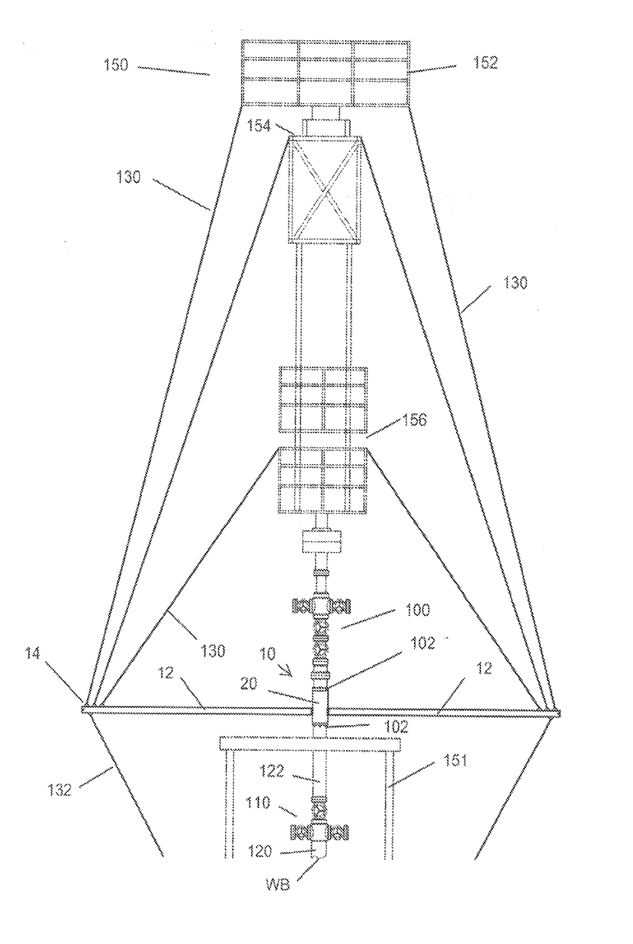
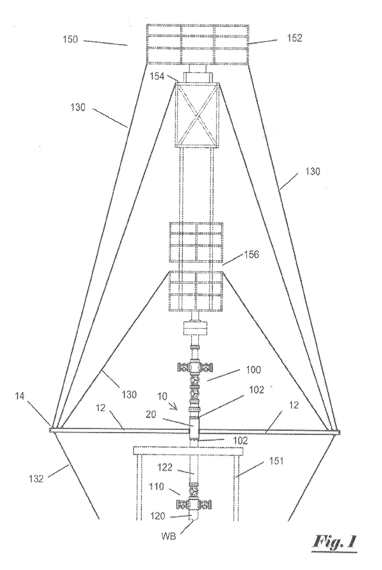
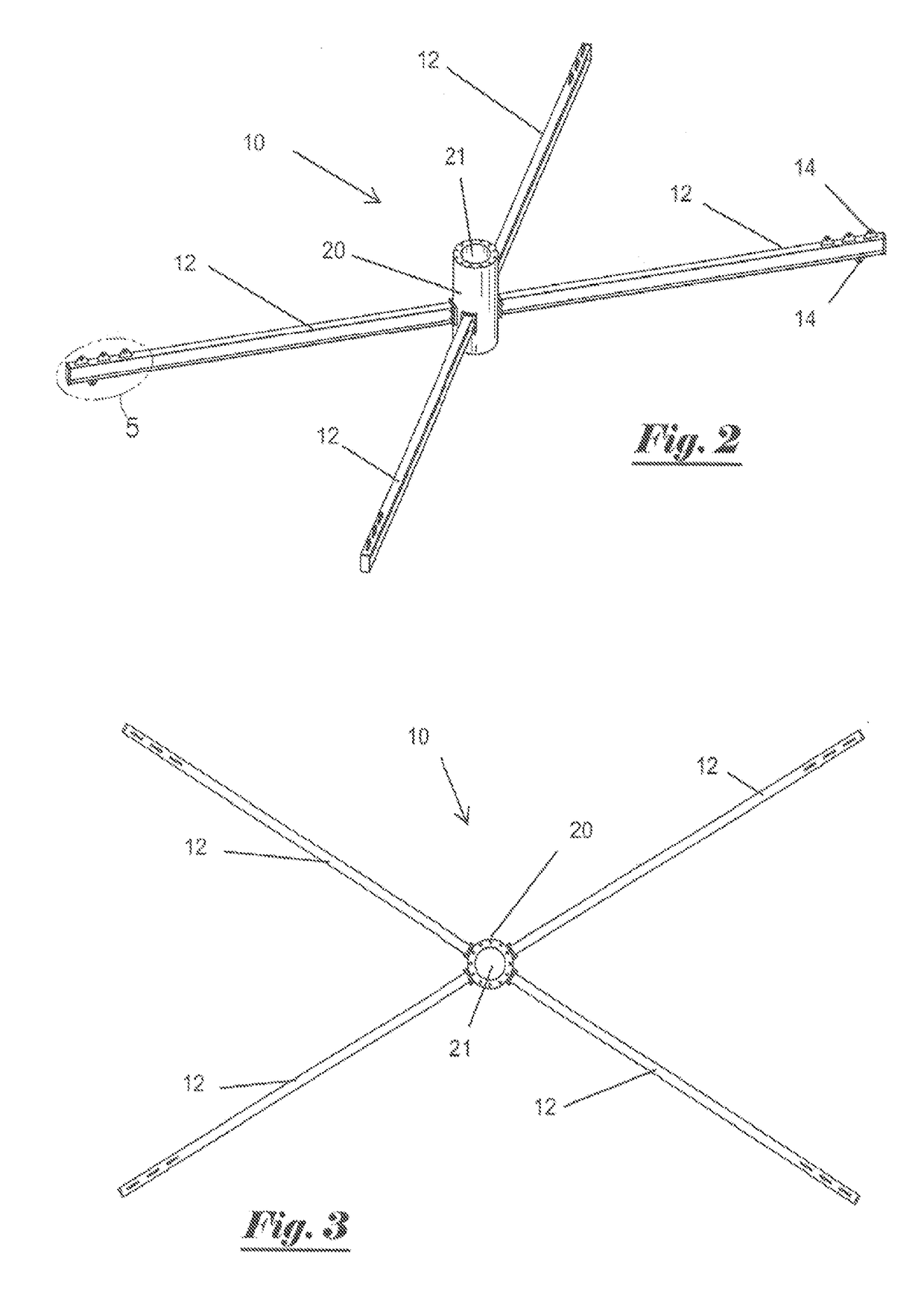
[0030]FIG. 1 suggests one embodiment of the invention, an anchor assembly including a spool body and a beam support assembly. FIG. 1 shows one embodiment of the spool body 10 (also sometimes referred to as the “anchor spool”10) mounted on casing string 120 of wellbore WB at offshore well platform 151 in a position below BOP stack 100 and axially in line with the BOP stack 100 of the pressure containment system 110 of wellbore WB. The anchor spool 10 has a plurality of detachable, radially extending, cantilevered support beams 12. The support beams are “cantilevered” in one sense by the fact that their distal ends do not have legs extending to a land or subsea surface from which the well stack (as defined below) extends. The anchor spool 10 with the support beams 12 provide a temporary support framework for attachment of guide members 130 extending from the workbasket 152, snubbing jack 154, and work window 156 of snubbing unit 150 mounted upon the BOP stack 100. Guywires 132 may be ...


PUM


Abstract

A tubular anchor spool having a plurality of removably attached, radially extending, support beams removably attached to a BOP stack of a wellbore to provide a temporary support framework for workover equipment such as a snubbing unit. Guywires are attached to the support beams of the temporary framework for support of the workover equipment. The anchor spool is fabricated offsite and delivered to the well site for installation.

Description

CROSS REFERENCE TO RELATED APPLICATION[0001]This application is a continuation-in-part of PCT / US2015 / 035581 filed Jun. 12, 2015, which is incorporated by reference herein in its entirety.FIELD OF THE INVENTION[0002]This invention relates to offshore drilling and production of oil and gas. More specifically, the invention relates to a temporary support assembly for workbaskets or other platforms used for well workover operations at a well site such as snubbing operations, coiled tubing operations, and other wellbore applications.BACKGROUND[0003]A stack of wellbore blowout preventers (BOP stack) incorporated with the riser piping of a wellbore casing system maintains and controls pressure in the wellbore of an oil and gas well. Often it is necessary to perform well workover operations such as snubbing. Snubbing is the process of running or inserting pipe into the wellbore with specialized equipment called a snubbing unit when the blowout preventers of the BOP stack are controlling wel...

Claims


Application Information

Patent Timeline
IPC IPC(8): E21B41/00E21B33/03
CPCE21B41/00E21B33/03E21B19/00E21B15/00
Inventor HARDY, MARK JAMES
Owner HARDY MARK JAMES
Learn More