Example 1, Comparative Examples 1 and 2
[0113]2.19 parts by mass of polyvinylpyrrolidone (K30, manufactured by Nippon Shokubai Co., Ltd.) as a water-soluble polymer, 0.13 parts by mass of an additive compound that is a type disclosed in Table 1, and 0.18 parts by mass of benzyltrimethylammonium hydroxide as a basic compound were dissolved in ion-exchanged distilled water (97.5 parts by mass) to prepare a coating agent.
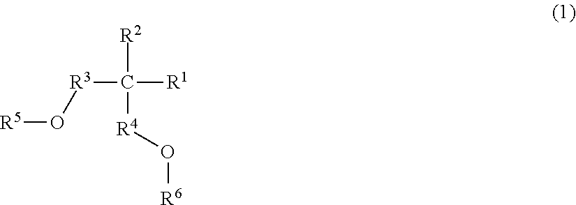
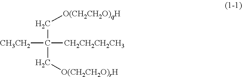
[0114]In Example 1, Compound 1 represented by the following formula was used as additive compound.
(In the above formula, the sum of q and r represents 4 as the average addition numbers of ethylene oxide.) In Comparative Examples 1 and 2, the following Comparative
[0115]Compounds 1 and 2 were used as the additive compound. Comparative Compound 1: a compound represented by the following formula:
(In the above formula, —C12H25 represents an n-dodecyl group, and the sum of a and b represents 13 on average.) Comparative Compound 2: a compound represented by the following formula:
(In the above formula, t represents 11 on average.)
(Evaluation)
[0116]After applying an antireflective-film coating liquid (Brewer Science Inc., ARC-29A) on a 12-inch silicon wafer, it was heat-treated for 60 seconds at 205° C. to provide an antireflective film having a film thickness of 89 nm. After applying a positive-type resist composition (Tokyo Ohka Kogyo Co., Ltd., TARF-PI6-144ME) on this antireflective film using a spinner, it was heat-treated for 60 seconds at 120° C. to form a resist film having a film thickness of 90 nm. Exposure treatment was performed on the resist film formed as described above through a mask for forming a line- and space pattern with lines and spaces each having a width of 50 nm, and then heat treatment was performed at 90° C. for 60 seconds. Then, development treatment was performed with a 2.38 mass % aqueous solution of TMAH (tetramethylammonium hydroxide), and then a rinse with ion-exchanged distilled water was performed to obtain a line-and-space pattern.
[0117]The coating agents of Examples or Comparative Examples were each applied on the surface of a substrate having a line-and-space pattern using a spinner so that the film thickness of a coat film became 60 nm to coat the surface of the line-and-space pattern with a coat film comprising the coating agent. Then, the line-and-space pattern coated with the coating agent was heated at 110° C. for 60 seconds to perform coating treatment of the line-and-space pattern. Subsequently, ion-exchanged distilled water was brought into contact with the coat film for 100 seconds for removal of the coat film from the surface of the line-and-space pattern. The following evaluations were performed for the resulting line-and-space pattern subjected to coating treatment.
[Evaluation of the Reduction Amount of Line Width Roughness (LWR)]
[0118]First, the line-and-space pattern before performing coating treatment was observed under a scanning electron microscope to measure line widths at 400 locations. The standard deviation (σ) in line width was computed from the values of line widths at 400 locations. Subsequently, a 3-fold value (3σ) of the standard deviation was computed, and the value of 3σ was taken as the roughness (LWR1, nm) of the lines in the untreated line-and-space pattern. For each of the line-and-space patterns subjected to coating treatment using the coating agents of Examples and Comparative Examples, the roughness (LWR2, nm) of the lines in the line-and-space pattern subjected to coating treatment was also computed as in LWR1. From LWR1 and LWR2 computed, the reduction amount of LWR, ΔLWR (nm) was computed according to the following expression.
ΔLWR=LWR1−LWR2
Table 1 shows the reduction amounts of LWR, ΔLWR for the line-and-space patterns subjected to coating treatment using the coating agents of Examples and Comparative Examples. Note that a negative value of ΔLWR means that the LWR, which is an index for variations in the line width, after coating treatment with the coating agent is increased as compared with the untreated LWR.
[Evaluation of the reduction amount of line edge roughness (LER)]
[0119]The line-and-space pattern before performing coating treatment was observed under a scanning electron microscope to measure line edge widths (the variation from the standard line) at 100 locations. The standard deviation (a) in line edge widths was computed from the values of line edge widths at 100 locations. Subsequently, a 3-fold value (3a) of the standard deviation was computed, and the value of 3a was taken as the line edge roughness (LER1, nm) of the lines in the untreated line-and-space pattern. For each of the line-and-space patterns subjected to coating treatment using each of the coating agents of Examples and Comparative Examples, the line edge roughness (LER2, nm) in the line-and-space pattern subjected to coating treatment was also computed as in LER1. From LER1 and LER2 computed, the reduction amount of line edge roughness (LER), ΔLER (nm) was computed according to the following expression.
ΔLER=LER1−LER2
Table 1 shows the reduction amounts of LER, ΔLER for the line-and-space patterns subjected to coating treatment using the coating agents of Examples and Comparative Examples. Note that a negative value of ΔLER means that the LER, which is an index for variations in the smoothness of a side of a line (in other words, an index for the roughness of a side of a line), after coating treatment with the coating agent is increased as compared with the untreated LER.
[Evaluation of the Reduction Amount of Line Widths]
[0120]First, the line-and-space pattern before performing coating treatment was observed under a scanning electron microscope to measure line widths at 400 locations. The mean value of line width values at 400 locations was calculated, and the calculated mean value was taken as a line width W1 (nm). For each of the line-and-space patterns subjected to coating treatment using the coating agents of Examples or Comparative Examples, the mean value of line widths at 400 locations was also calculated, and the calculated mean value was taken as a line width W2 (nm). From W1 and W2 computed as described above, the reduction amount of line width ΔW (nm) was computed according to the following expression.
ΔW=W1−W2
Table 1 shows the reduction amount of line width ΔW for the line-and-space pattern subjected to coating treatment using each of the coating agents of Examples and Comparative Examples.
TABLE 1 Reduction Reduction Reduction amount of amount of amount of Additive LWR LER LWR LER Line width line width compound (nm) (nm) (nm) (nm) (nm) (nm) Reference None 4.57 3.07 — — 50.2 — Example 1 (Without treatment) Example 1 Compound 1 4.49 2.97 0.08 0.10 48.3 1.9 Comparative Comparative 4.66 3.12 −0.09 −0.05 44.1 6.1 Example 1 Compound 1 Comparative Comparative 4.75 3.14 −0.18 −0.07 44.4 5.8 Example 2 Compound 2
[0121]Example 1 reveals that in a case where a positive-type resist pattern is treated by a predetermined method using a coating agent that is an aqueous solution containing a water-soluble polymer (resin) and Compound 1 as the quaternary carbon-atom-containing compound (B), both of LWR and LER roughness of the positive-type resist pattern can be reduced. Comparative Example 1 and 2 reveal that in a case where a positive-type resist pattern is treated by a predetermined method using a coating agent that is an aqueous solution containing a water-soluble polymer (resin) and Comparative Compound 1 or 2 neither of which is the quaternary carbon-atom-containing compound (B), neither LWR nor LER roughness of the positive-type resist pattern can be reduced. Note that the reduction amount of line width was low in a case where the coating agent of Example 1 was used compared to a case where the coating agent of Comparative Example 1 or 2 was used.