Vehicle air-conditioning apparatus
- Summary
- Abstract
- Description
- Claims
- Application Information
AI Technical Summary
Benefits of technology
Problems solved by technology
Method used
Image

Examples
first embodiment
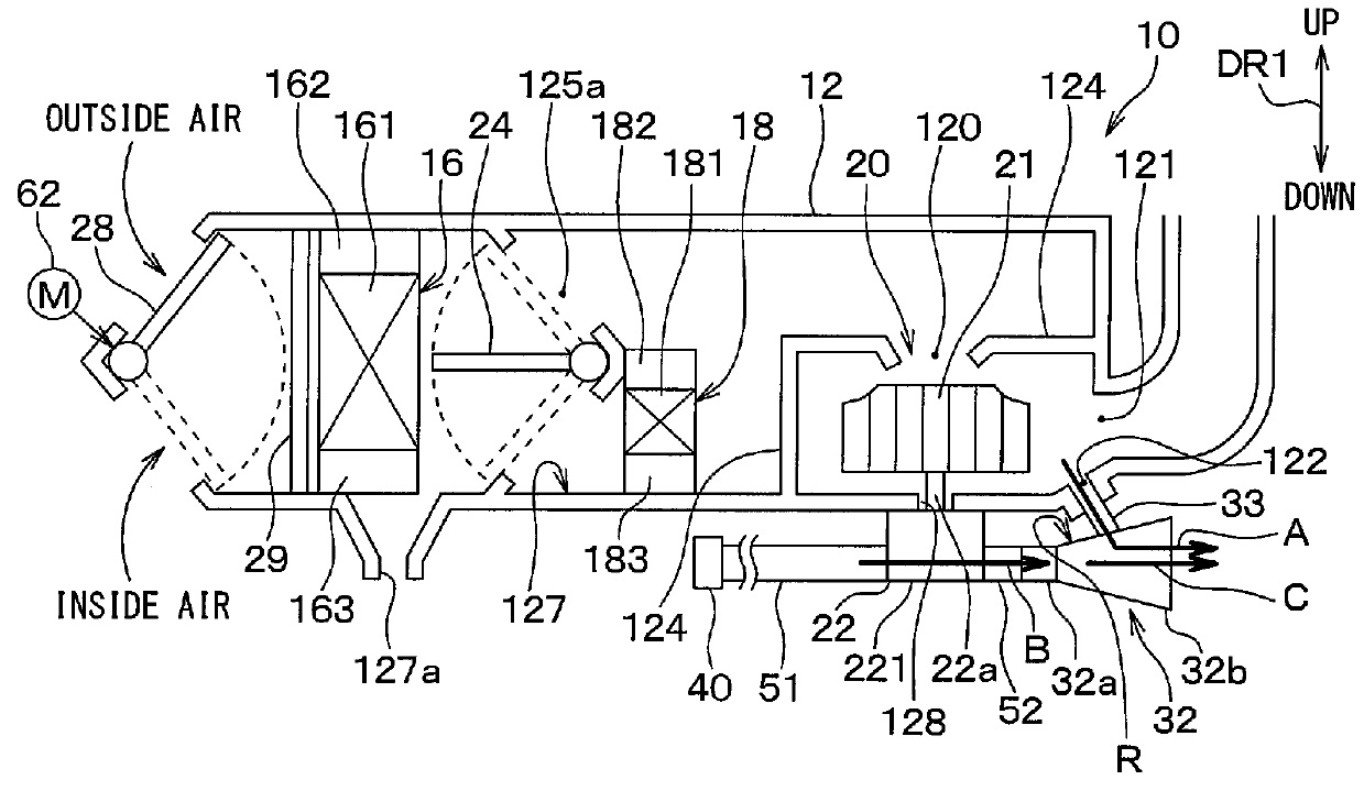
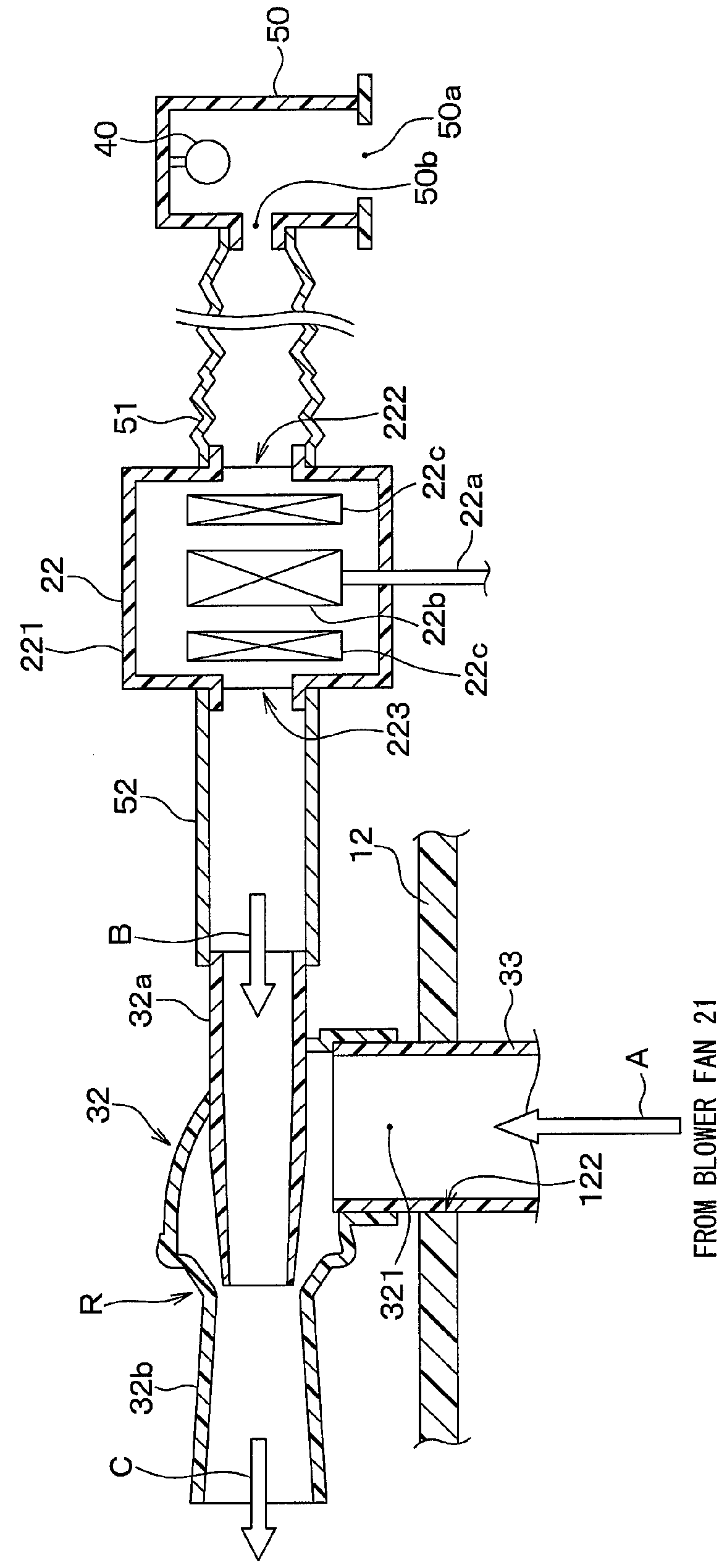
[0018]A vehicle air-conditioning apparatus 10 according to a first embodiment of the present disclosure will be described referring to FIGS. 1, 2. FIG. 1 is a cross-sectional diagram illustrating a main structure of the vehicle air-conditioning apparatus 10 according to the present embodiment. In FIG. 1, an inside air temperature sensor 40, an aspirator 32 that generates a flow in an air around the inside air temperature sensor 40, for example, are illustrated schematically. In FIG. 1, respective up and down arrows DR1 indicate the directions in a vehicle-mounted state where the vehicle air-conditioning apparatus 10 is mounted in a vehicle. That is, both end-arrows DR1 shown in FIG. 1 denote the up and down directions of the vehicle.
[0019]The vehicle air-conditioning apparatus 10 shown in FIG. 1 configures a part of a vehicle air conditioner including a compressor and a condenser that are disposed in an engine room of the vehicle. The vehicle air-conditioning apparatus 10 is dispose...
second embodiment
[0068]A vehicle air-conditioning apparatus 10 of a second embodiment of the present disclosure will be described referring to FIG. 3. FIG. 3 is a cross-sectional diagram illustrating a main structure of the vehicle air-conditioning apparatus 10 of the present embodiment. In FIG. 3, an inside air temperature sensor 40 is omitted, but the inside air temperature sensor 40 is disposed in the sensor accommodation portion 50 provided in the instrument panel of the vehicle in the present embodiment. As in the first embodiment, the sensor accommodation portion 50 housing the inside air temperature sensor 40 is connected to the electronic motor 22 through the hose 51 having a bellows shape.
[0069]The vehicle air-conditioning apparatus 10 of the above-described first embodiment includes the blower 20 having one blower fan 21, but the vehicle air-conditioning apparatus 10 of the present embodiment includes the blower 20 having two blower fans 21a, 21b. The blower 20 of the present embodiment is...
third embodiment
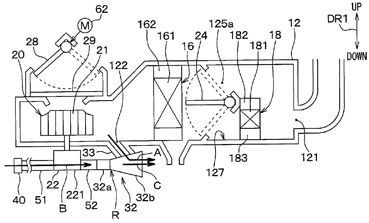
[0083]A vehicle air-conditioning apparatus 10 according to a third embodiment of the present disclosure will be described referring to FIG. 4. FIG. 4 is a cross-sectional diagram illustrating a main structure of the vehicle air-conditioning apparatus 10 of the present embodiment.
[0084]The vehicle air-conditioning apparatus 10 of the above-described first embodiment has a suction-type layout in which the blower 20 is located downstream of the evaporator 16 and the heater core 18. In contrast, the vehicle air-conditioning apparatus 10 of the present embodiment has a pushing-type layout in which the blower 20 is located upstream of the evaporator 16 and the heater core 18.
[0085]The air-conditioning case 12 has the opening portion 122 through which the air blown by the blower fan 21 is discharged, and the opening portion 122 communicates with the aspirator 32 through the duct 33.
[0086]In such configurations, when the blower 20 is actuated, the outside air that is an air outside the vehi...
PUM
 Abstract
Description
Claims
Application Information
 - R&D Engineer
- R&D Manager
- IP Professional
- Industry Leading Data Capabilities
- Powerful AI technology
- Patent DNA Extraction
Browse by: Latest US Patents, China's latest patents, Technical Efficacy Thesaurus, Application Domain, Technology Topic.
© 2024 PatSnap. All rights reserved.Legal|Privacy policy|Modern Slavery Act Transparency Statement|Sitemap