

Accelerator pedal unit for a vehicle
- Summary
- Abstract
- Description
- Claims
- Application Information
AI Technical Summary
Benefits of technology
Problems solved by technology
Method used
Image

Examples
Embodiment Construction
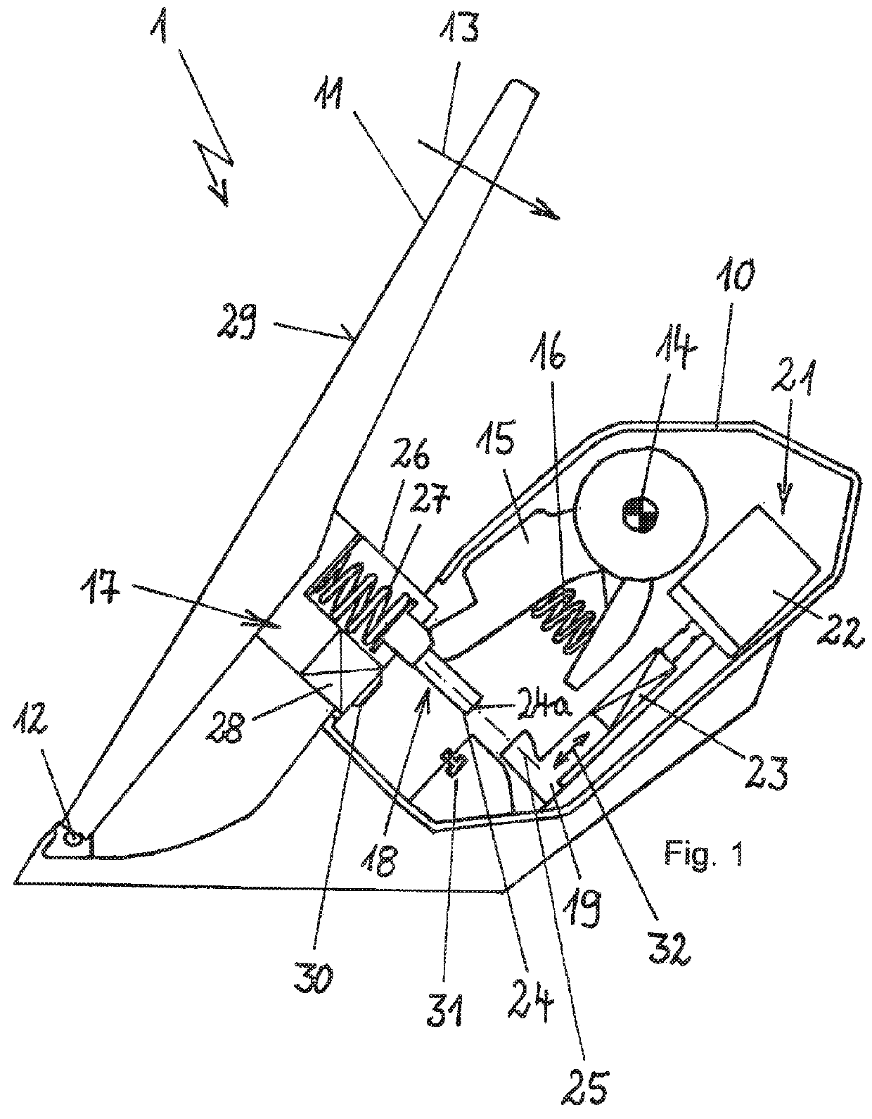
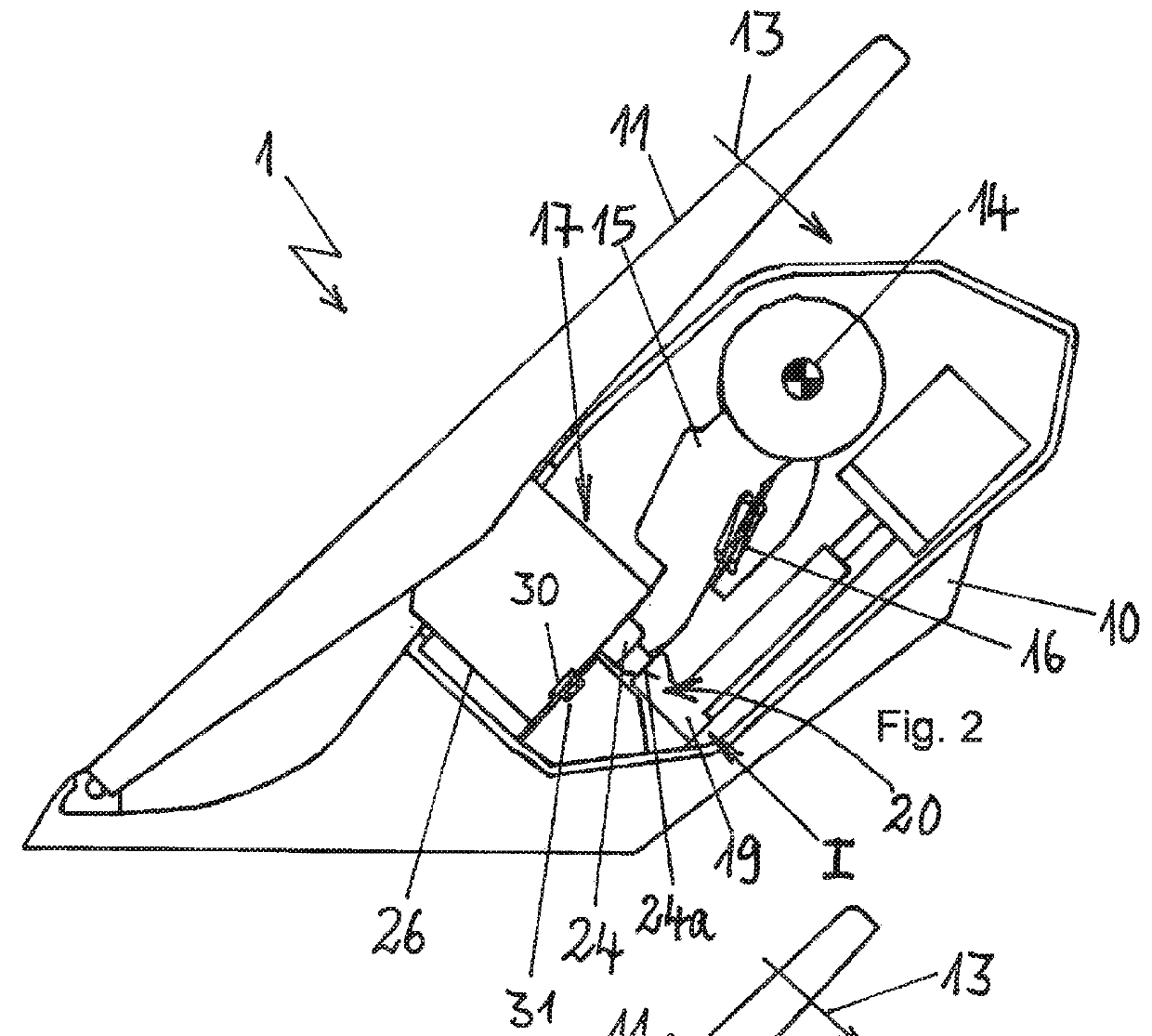
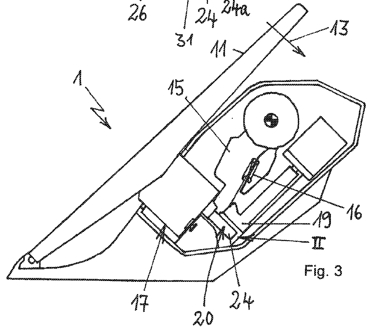
[0032]In a schematic side view, FIG. 1 shows the accelerator pedal unit 1 for a motor vehicle having a base body 10, on which an accelerator pedal 11 is received rotatably mounted in a rotary joint 12. When the accelerator pedal 11 is activated, it moves from the shown starting position along a direction of actuation 13, wherein the accelerator pedal 11 is moved towards the base body 10. In this case, a sensor unit 14 is activated via a feeler element 15, which is designed lever-like, in a manner not further shown, and via the sensor unit 14, the position of the accelerator pedal can be sensed along the direction of actuation 13. This way, an accelerator pedal signal is provided to a control unit via which, in a manner generally known, the driving speed of the motor vehicle can be specified.
[0033]A return spring 16 is shown in order to prestress the accelerator pedal 11 in the direction of a starting position, which the accelerator pedal 11 occupies when no actuation of the accelera...
PUM
 Abstract
Description
Claims
Application Information