Air vent for welded portion in plastic corrugated material and process for forming welded portion

a technology of plastic corrugated material and air vent, which is applied in the field of reusable plastic corrugated containers, can solve the problems of not being able to be re-used in the automated packaging line designed to work with new, and affecting the quality of paper boxes

Active Publication Date: 2018-04-19
ORBIS CORP
View PDF19 Cites 16 Cited by
  • Summary
  • Abstract
  • Description
  • Claims
  • Application Information

AI Technical Summary

Benefits of technology

[0018]The present invention provides an improved plastic corrugated box manufacturing process resulting in a plastic corrugated box with safe rounded sealed edges on the edges most frequently contacted by human hands. Sealing is desirable, particularly in certain applications such as transport and storage of food items. Sealing prevents food, insects, water, or other contaminants or debris from entering the interstices of the flutes in the corrugated material, and bacteria or mold from growing therein.
[0019]The process of the present invention also allows for the creation of a manufacturer's joint (the connection between one end of a blank with the other end when forming the blank into a box shape) that reduces the amount of bowing in a stack of blanks. Preferably, the manufacturer's joint adds no additional thickness to each blank. The process also allows for major and minor flap score lines that allow the plastic corrugated material boxes to return to an original straight position for use in conventional automated packaging lines. The process of the present invention also provides a plastic corrugated blank that can be converted into a box using conventional paper corrugated converting equipment.
[0020]The process confers a number of advantages over the prior art. For example, the resulting edge seals and score lines can be performed in a more controlled and, therefore, consistent process. This results in a more robust plastic corrugated box. Additionally, the plastic corrugated boxes prepared in this manner can be die cut and assembled on conventional paper corrugated converting equipment, including rotary die cutters, and can be processed at higher speeds. Also, the plastic corrugated boxes are able to return to their original shape as the score lines formed by the present invention will have “memory” that return major and minor flaps to straight after each use.
[0023]In accordance with one embodiment of the invention, a plastic corrugated box which can be reused in box converting machinery is disclosed. The plastic corrugated box comprises at least a first side wall panel having a top portion and a bottom portion and a first bottom flap connected to the bottom portion of the first side wall panel by a first ultrasonically formed score line. It has been found that ultrasonically forming the score line of a plastic corrugated box reshapes the structure of the plastic in that area. The reshaped structure allows for folding the flap about the score line when forming a box, and provides sufficient memory to return the flap to a straight position (i.e., coplanar or aligned with the plane of the side wall panel) after use. This enables the corrugated box to be collapsed and then (along with a stack of other similar boxes) reformed into a box in a box converting apparatus. Such apparatuses require the flaps to be straight and coplanar or aligned with the side wall panels.
[0039]One unique aspect of the invention involves pre-sealing portions of the corrugated plastic material in certain areas of the blank prior to performing other operations. As used herein, “pre-sealing” (or “pre-sealed”) refers to crushing and / or welding or ironing the plastic so that it will no longer have memory to later revert to its original shape. This can include sufficiently melting some or all of the material in the area being pre-sealed. In effect, the pre-sealing bonds the two outer skins and intervening flutes of the material together so that the pre-sealed area maintains a permanently flattened state. Pre-sealing allows for forming a manufacturer's joint that does not (upon formation or later) increase the thickness of the blank. It also enables portions of the blank to be die cut more easily (e.g., for the flap slots) using conventional die cutting apparatuses, and with better results.

Problems solved by technology

After a paper corrugated blank is converted into a box and used, it cannot typically be re-used in automated packaging lines designed to work with new, straight and flat boxes.
This is in part because the major and minor flaps of a paper corrugated box will not return to their original vertical alignment after use, and in part because the creases and scores of a paper corrugated box lose integrity with each use.
In such instances, the flaps become floppy or limp.
Additionally, paper boxes cannot be washed or otherwise cleaned, and therefore cannot be reused in instances where sanitation is important (e.g., food items, etc.)
A lingering problem with current attempts to create a re-usable plastic corrugated container is that it must be able to return (after being used in a box form) to a flat state with the flaps aligned or coplanar with the side wall panels of the blank in order to be refolded in the box converting equipment.
Industry efforts to this point have failed to provide such a container.
However, the score lines cannot be made with too much memory so that after use, they have too much bounce-back or spring-back making them difficult for the converting equipment.
This forms a sealed, but sharp edge, which is not acceptably ergonomically safe in most applications.
Some limited success has been found using these processes for lighter densities of plastic corrugated material.
Thus, the demand for such containers will rise and the speed of the plastic container processing will become a more pressing issue.
The formation of various features in a plastic corrugated material can be problematic.
One challenge is encountered when attempting to crush or weld the outer layers of the material together.
In particular, air in the flute areas can be trapped resulting in air bubbles.
In severe cases, the air can burst through the edge or other portions of the material.

Method used


Image

  • Air vent for welded portion in plastic corrugated material and process for forming welded portion
  • Air vent for welded portion in plastic corrugated material and process for forming welded portion
  • Air vent for welded portion in plastic corrugated material and process for forming welded portion

Examples


Embodiment Construction

[0118]While this invention is susceptible of embodiments in many different forms, there is shown in the drawings and will herein be described in detail preferred embodiments of the invention with the understanding that the present disclosure is to be considered as an exemplification of the principles of the invention and is not intended to limit the broad aspect of the invention to the embodiments illustrated.

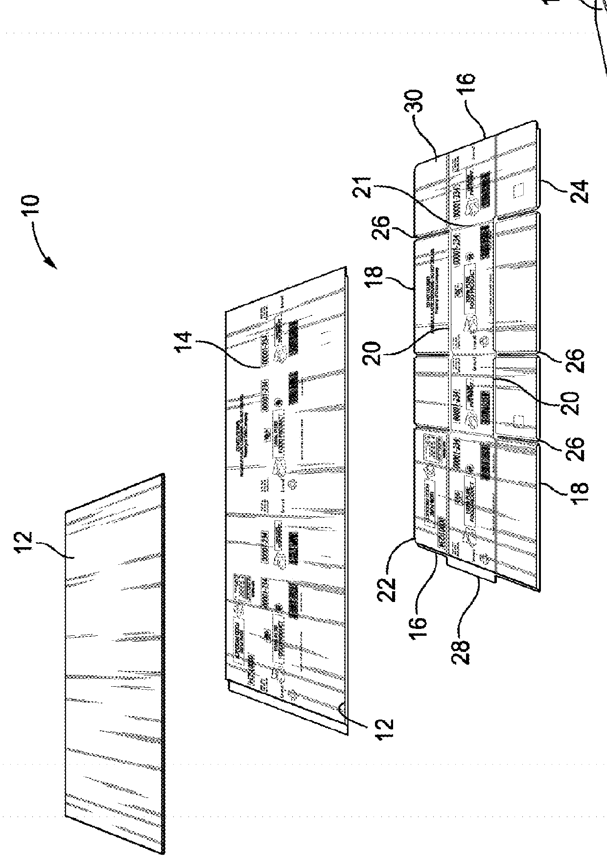
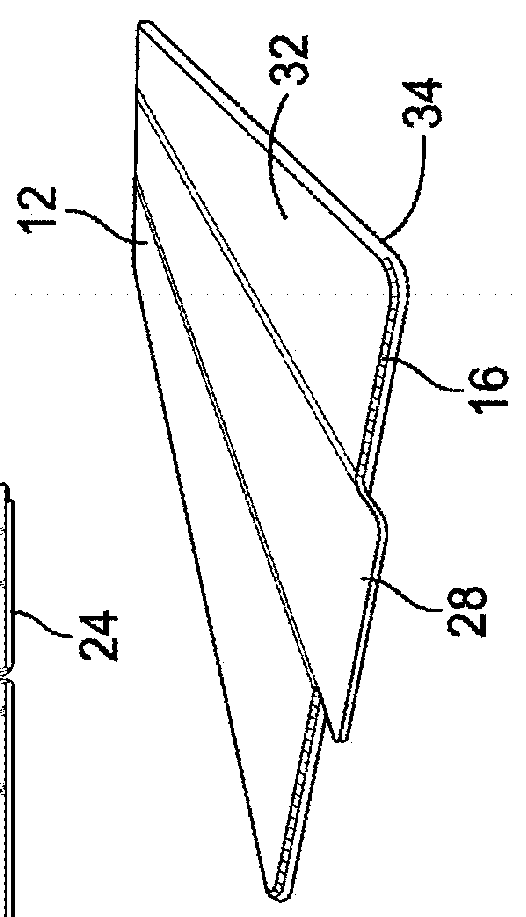
[0119]FIG. 1 illustrates a plurality 10 of progressively formed blanks 12 in a known method of forming plastic corrugated material into boxes using conventional converting equipment. The method includes the steps of obtaining a sized plastic corrugated blank 12, printing 14 thereon, if necessary, on one or both sides of the plastic corrugated blank 12, sealing the vertical edges 16 and the horizontal edges 18, forming scores (sometimes also referred to as scorelines) 20 therein and creating side wall panel fold lines 21 therein, and die cutting slots 26 for the major flaps 22 a...


PUM

PropertyMeasurementUnit
frequencyaaaaaaaaaa
frequenciesaaaaaaaaaa

Abstract

A corrugated plastic box and a method for manufacturing a corrugated plastic box from a blank are provided. The method includes the steps of forming rounded edge seals on the perimeter edges of the blank, pre-sealing portions of the blank—including providing air vents to allow trapped air to escape during the pre-sealing process—to form a plurality of areas in which major and minor flap slots and a glue tab are desired, ultrasonically scoring the blank to form a plurality of flap score lines, and cutting the blank through the plurality of pre-sealed flap slots and glue tab, leaving a sealed edge.

Description

CROSS-REFERENCE TO RELATED APPLICATIONS[0001]The present application is a continuation-in-part of U.S. patent application Ser. No. 14 / 580,810 filed Dec. 23, 2014, which claims the benefit of U.S. Provisional Application No. 61 / 920,570 filed Dec. 24, 2013; and also claims the benefit of U.S. Provisional Application No. 62 / 482,031 filed Apr. 5, 2017, the contents of which are incorporated herein by reference.FEDERALLY SPONSORED RESEARCH OR DEVELOPMENT[0002]N / ATECHNICAL FIELD[0003]The present invention generally relates to a reusable plastic corrugated container or more specifically box with smooth outer edges and sealed flap slots, and ultrasonically formed score lines, and to a process for manufacturing reusable plastic corrugated containers and boxes with smooth sealed outer edges and sealed flap slots, and having flap score lines that allow these containers and boxes to be used and reused in conventional paper corrugated packaging automation lines which may include case erectors, c...

Claims


Application Information

Patent Timeline
Patent Type & Authority Applications(United States)
IPC IPC(8): B65D5/42B65D5/02B31B50/04B31B50/20B31B50/26B31B50/64B31B50/73B31F1/20
CPCB65D5/4295B65D5/0281B65D5/4266B31B50/04B31B50/20B31B50/26B31B50/64B31B50/732B31F1/20B65D65/38B65D2301/20B31F1/10B31B50/22B31B50/146B31B50/256B31B2110/30B31B2100/0022Y02W30/80B29C51/006
Inventor MCMAHON, WILLIAM F.BALAZS, DONALD J.PETERSON, GREGORY A.
Owner ORBIS CORP
Why Eureka
Try Eureka