Matching device and matching method

a technology of matching device and matching method, which is applied in the field of matching, can solve problems such as the algorithm of such a conventional techniqu

Active Publication Date: 2018-04-26
KOKUSA ELECTRIC CO LTD
View PDF0 Cites 17 Cited by
  • Summary
  • Abstract
  • Description
  • Claims
  • Application Information

AI Technical Summary

Benefits of technology

[0019]As described above, in the matching algorithm of the conventional technique, there may be no converge on a matching point depending on the load i

Problems solved by technology

The algorithm of such a conventional technique is disadvantageous in that VC1

Method used


Image

  • Matching device and matching method
  • Matching device and matching method
  • Matching device and matching method

Examples


first embodiment

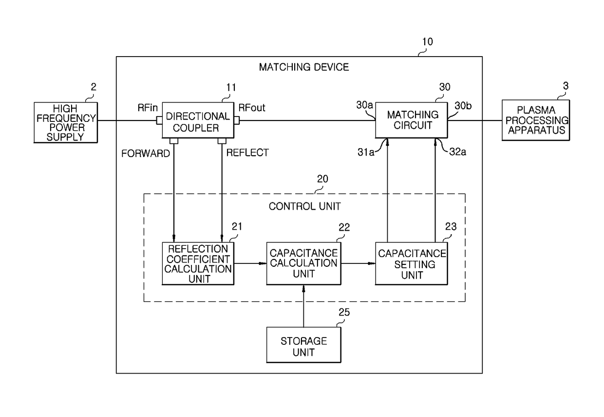
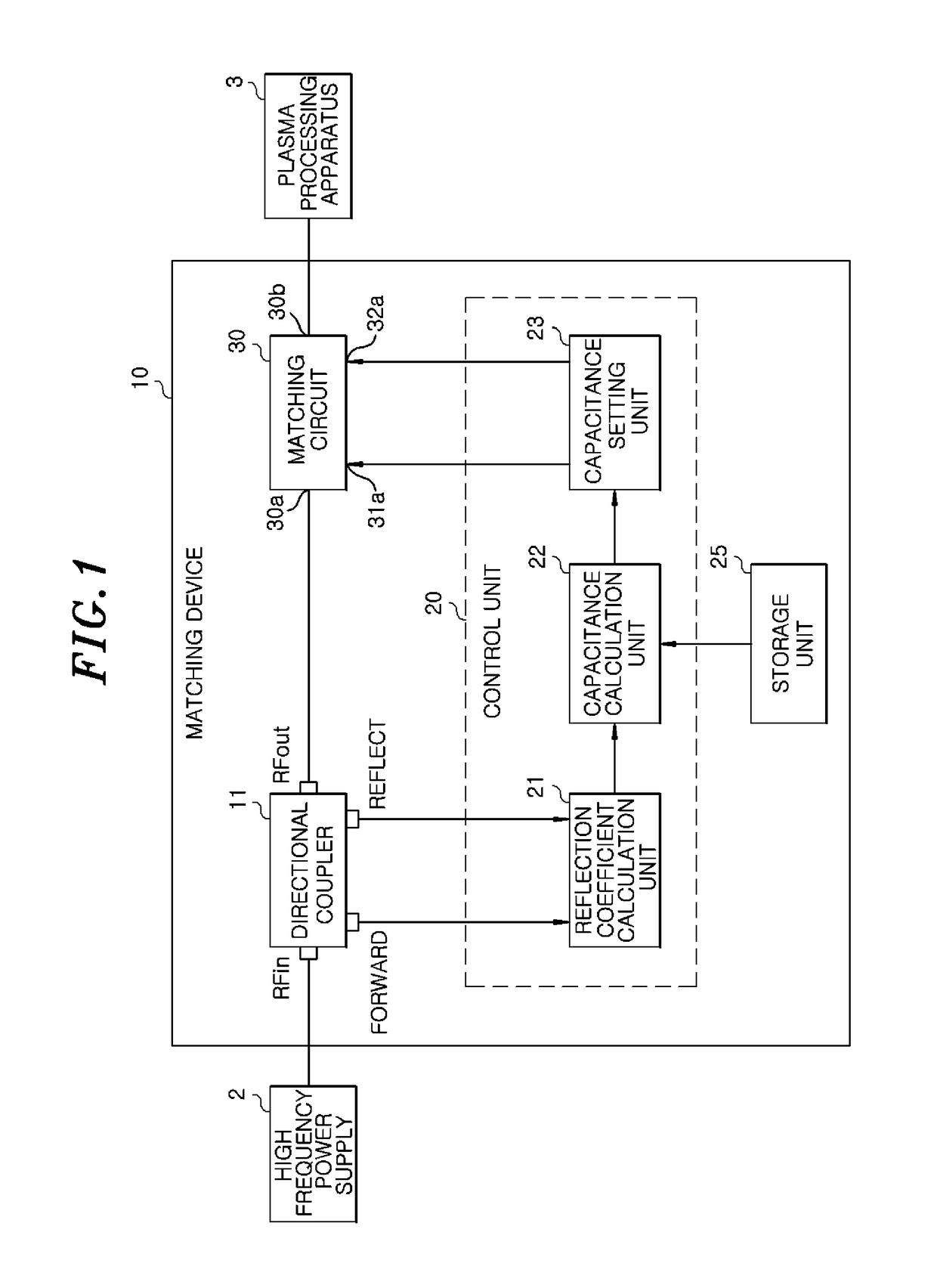
[0038]Hereinafter, a first embodiment (embodiment 1) of the present invention will be described with reference to the accompanying drawings. FIG. 1 is a block diagram of a matching device 10 according to the first embodiment. Like reference numerals used in FIGS. 1 and 7 designate like parts, and redundant description thereof will be omitted.

[0039]The matching device 10 includes a directional coupler 11 for detecting a travelling wave and a reflected wave, a matching circuit 30 having a matching element for matching an impedance between a RF generator 2 and a plasma processing apparatus 3, a control unit 20 for controlling a circuit constant of the matching element of the matching device 10, and a storage unit 25.

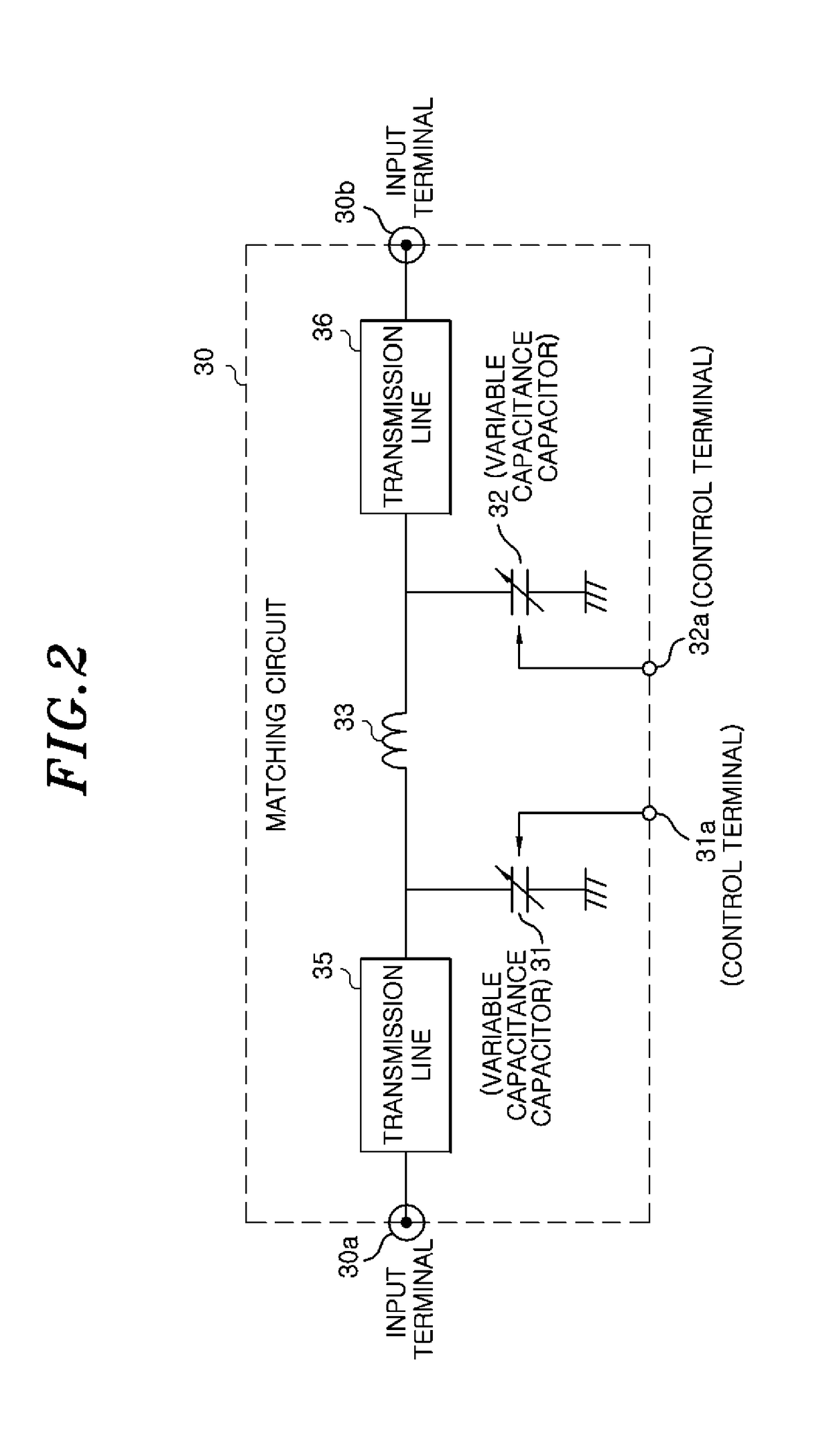
[0040]As described above with reference to FIG. 2, the matching circuit 30 includes the input terminal 30a, the output terminal 30b, the first variable capacitance capacitor 31 having one end connected to the input terminal 30a through the transmission line 35 and the other...

second embodiment

[0077]A matching device according to a second embodiment provides a technique for adapting circle matching to a dynamic load as a solution to the above drawbacks (1) to (3). A configuration of the matching device according to the second embodiment will be described with reference to FIG. 9. A matching device 10A according to the second embodiment is different from the matching device 10 of the first embodiment in the processing of the capacitance calculation unit 22, i.e., the control of the capacitance VC1 of the variable capacitance capacitor 31 of the matching circuit 30 and the capacitance VC2 of the variable capacitance capacitor 32 of the matching circuit 30. The other configurations of the matching device 10A of the second embodiment are the same as those of the matching device 10 of the first embodiment. In other words, the capacitance calculation unit 22A of the matching device 10A of the second embodiment has following features in addition to the features of the capacitanc...

example 1

[0101]A first example (Example 1) of predictive control of VC2 will be described with reference to FIG. 12. FIG. 12 explains predictive control in the Example 1. An intersection point between a circumference and a straight line extending through two points in the control of VC2 on the U, V coordinates is calculated and set to a target point (expected point on circumference). Specifically, as shown in FIG. 12, when two points in the VC2 control are positioned within a dashed ellipse A, an intersection point CL1 between a circumference R and a straight line L1 extending through the two points in the dashed ellipse A is calculated and set to the expected point on circumference. Similarly, when two points in the VC2 control are positioned within a dashed ellipse B, an intersection point CL2 between the circumference R and a straight line L2 extending through the two points in the dashed ellipse B is calculated and set to the expected point on circumference. Since the target value (expec...


PUM


Abstract

A matching device includes: a directional coupler that detects a traveling wave and a reflected wave; a matching circuit that has a first variable capacitance capacitor, a second variable capacitance capacitor and an inductance; and a control unit that calculates a reflection coefficient based on the traveling wave and the reflected wave and controls a capacitance value VC1 of the first variable capacitance capacitor and a capacitance value VC2 of the second variable capacitance capacitor. The control unit changes VC2 such that VC2 moves toward a circle drawn by the trajectory of the reflection coefficient passing through a matching point on a Smith chart, fine-tunes VC1 on the basis of a predicted intersection point with the circle, and when the distance between the calculated reflection coefficient and the circle becomes a predetermined value or less, changes VC1 such that the calculated reflection coefficient approaches zero, and fine-tunes VC2.

Description

FIELD OF THE INVENTION[0001]The present invention relates to a matching device for matching an output of a RF (Radio Frequency) generator and a load.BACKGROUND OF THE INVENTION[0002]A plasma processing apparatus is used in a semiconductor manufacturing process for performing etching or thin film formation. As for a power supply source of the plasma processing apparatus, a RF generator is used. In order to efficiently supply power from the RF generator to the plasma processing apparatus, it is required to match an impedance between the RF generator and the plasma processing apparatus (load). Generally, a matching device is interposed, as a unit for matching an impedance, between the RF generator and the plasma processing apparatus as described in, e.g., Patent Document 1.[0003]FIG. 7 is a functional block diagram of a conventional matching device 100. Referring to FIG. 7, the matching device 100 is interposed between a RF generator 2 and a plasma processing apparatus 3. A plasma is g...

Claims


Application Information

Patent Timeline
IPC IPC(8): H03H7/38H01P5/18H01J37/32
CPCH03H7/383H01P5/18H01J37/32183H03H7/40H03H11/30H05H2242/26H05H1/46
Inventor FUJIMOTO, NAOYAOSHIDA, YOSHIYUKIKATO, NORIKAZU
Owner KOKUSA ELECTRIC CO LTD
Why Eureka
Try Eureka