Railway vehicle body structure and manufacturing process thereof

a technology for railway vehicles and body structures, applied in the direction of manufacturing tools, transportation and packaging, non-electric welding apparatus, etc., can solve the problems of high cost, complicated, galvanic corrosion, etc., and achieve the effect of easy and cheap manufacturing

Active Publication Date: 2018-05-03
ALSTOM TRANSPORT TECH SAS
View PDF4 Cites 0 Cited by
  • Summary
  • Abstract
  • Description
  • Claims
  • Application Information

AI Technical Summary

Benefits of technology

[0005]Accordingly, the invention aims to remedy the aforementioned disadvantages of the prior art and proposes a new body struc

Problems solved by technology

However, welding steel elements to aluminum elements requires special precautions, insofar as these materials are difficult to weld together and tend to generate galvanic corrosion when they are brought into contact with each oth

Method used


Image

  • Railway vehicle body structure and manufacturing process thereof
  • Railway vehicle body structure and manufacturing process thereof
  • Railway vehicle body structure and manufacturing process thereof

Examples


Embodiment Construction

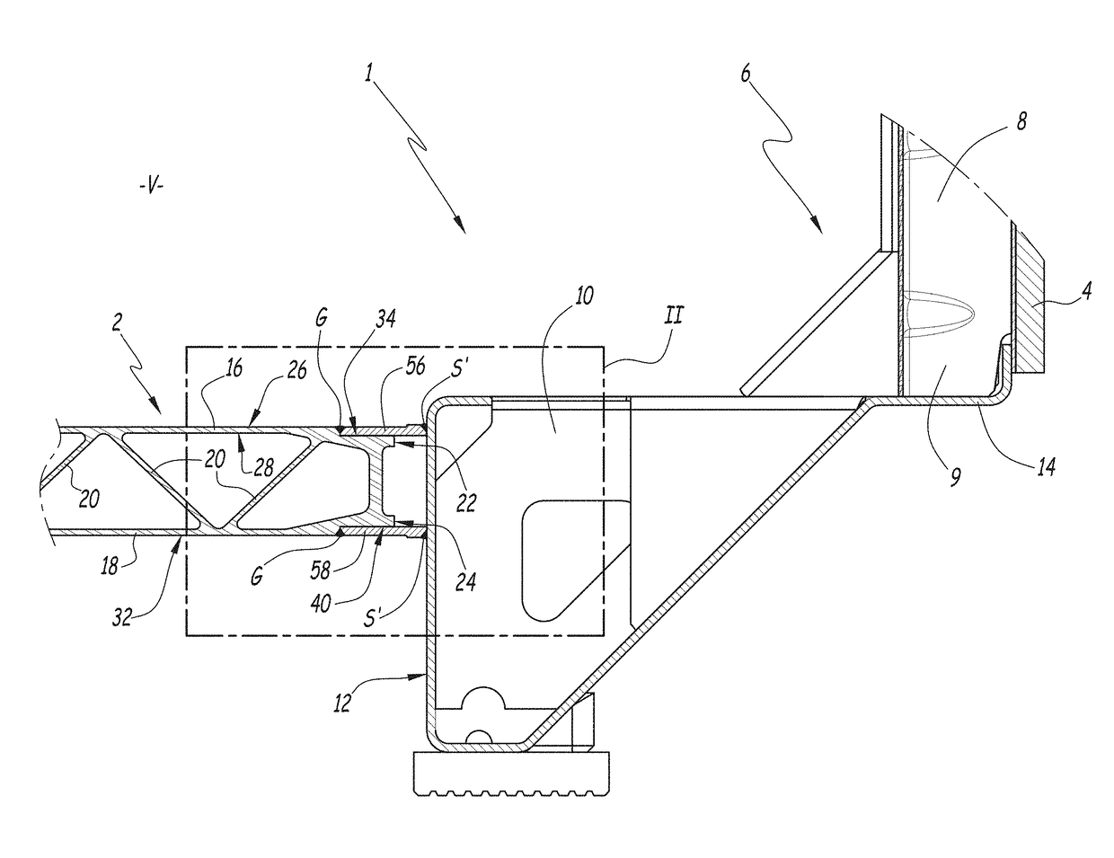
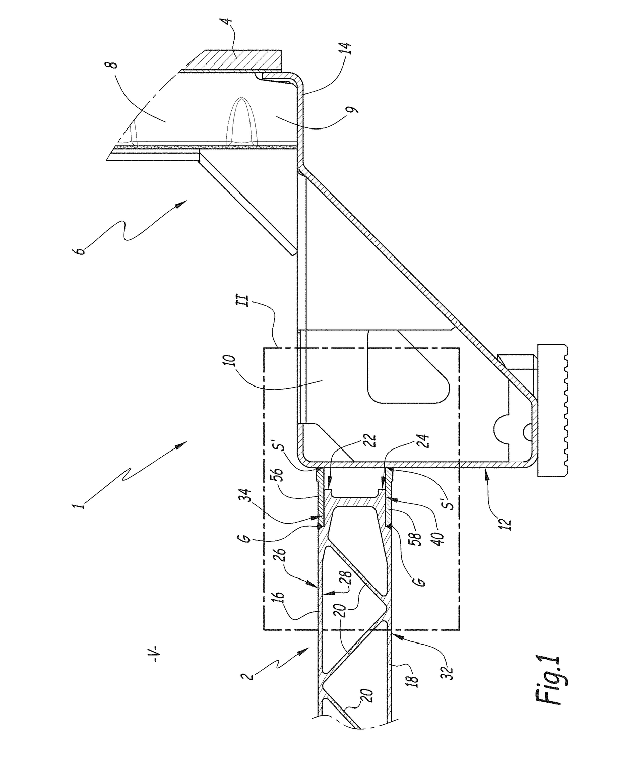
[0025]In the following, the sectional plane of FIGS. 1 to 3 is referred to as a “transverse plane”, so that the terms “longitudinal” and “length” designate an orthogonal, or at least intersecting, direction with respect to this transverse plane. Moreover, the terms “upper” and “top” refer to an upwardly-directed transverse direction in FIGS. 1 to 3, while the terms “lower” and “bottom” designate an opposite transverse direction. Finally, the terms “horizontal” and “vertical” respectively designate horizontal and vertical directions under normal conditions of use of the vehicle, when the latter is resting on rails: in this case, the horizontal direction is represented horizontally in the figures, while the vertical direction is shown vertically.

[0026]The structure 1 of FIGS. 1 and 2 belongs to a body of a rail vehicle, of the wagon, carriage or locomotive type, intended, for example, to form a part of the composition of a train.

[0027]The term “body” refers to the upper part of the ve...


PUM

PropertyMeasurementUnit
Frictionaaaaaaaaaa

Abstract

Disclosed is a body structure for a rail vehicle, wherein the body structure includes: a frame, which includes at least one support element made at least predominantly of steel alloy; and at least one equipment element made predominantly of aluminum alloy, and including at least one first plate having at least one longitudinal edge and a first surface delimited by the longitudinal edge. The body structure is wherein it further includes at least one longitudinal batten of steel alloy, which is integral with the support element, wherein the longitudinal batten is fixed flat to the first face by way of friction melt bonding.

Description

BACKGROUND OF THE INVENTIONField of the Invention[0001]The present invention relates to a body structure for a railway vehicle and a method for manufacturing such a body structure.Description of the Related Art[0002]To make a body structure of a railway vehicle, such as a carriage or a wagon, it is known to assemble elements made of different metallic materials in order to optimize the weight of the body. In particular, the floors of the structure may be made of aluminum, while other parts, such as the support trusses of the floors, are made of steel. In order to ensure the solidity and the longevity of the structure, it is preferable to join together the various elements that compose it by welding. However, welding steel elements to aluminum elements requires special precautions, insofar as these materials are difficult to weld together and tend to generate galvanic corrosion when they are brought into contact with each other.[0003]FR-A1-2 630 698 discloses a vehicle, provided with...

Claims


Application Information

Patent Timeline
IPC IPC(8): B61D17/04B61D17/10
CPCB61D17/043B61D17/041B61D17/10B23K20/122
Inventor ROLL, STEPHANEDELPHIGUE, BRUNO
Owner ALSTOM TRANSPORT TECH SAS
Why Eureka
Try Eureka