
Display Device

Active Publication Date: 2018-05-03
LG DISPLAY CO LTD
View PDF1 Cites 25 Cited by
  • Summary
  • Abstract
  • Description
  • Claims
  • Application Information

AI Technical Summary

Benefits of technology

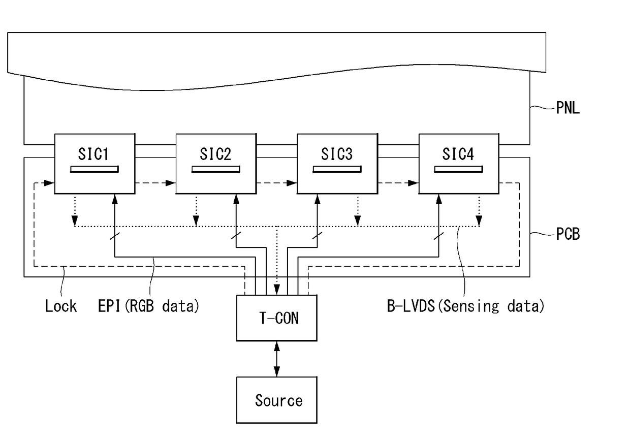
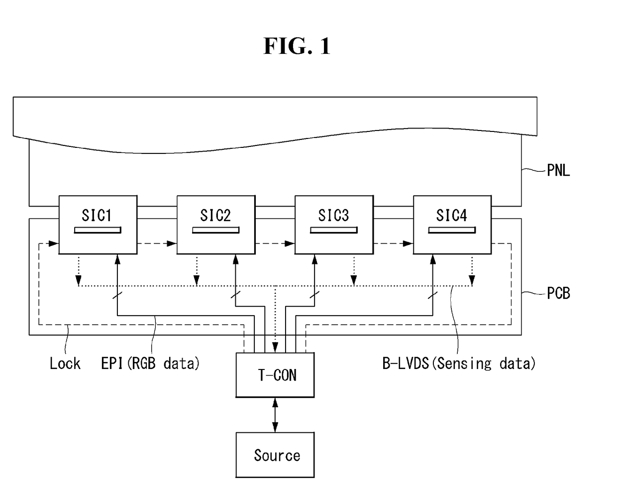
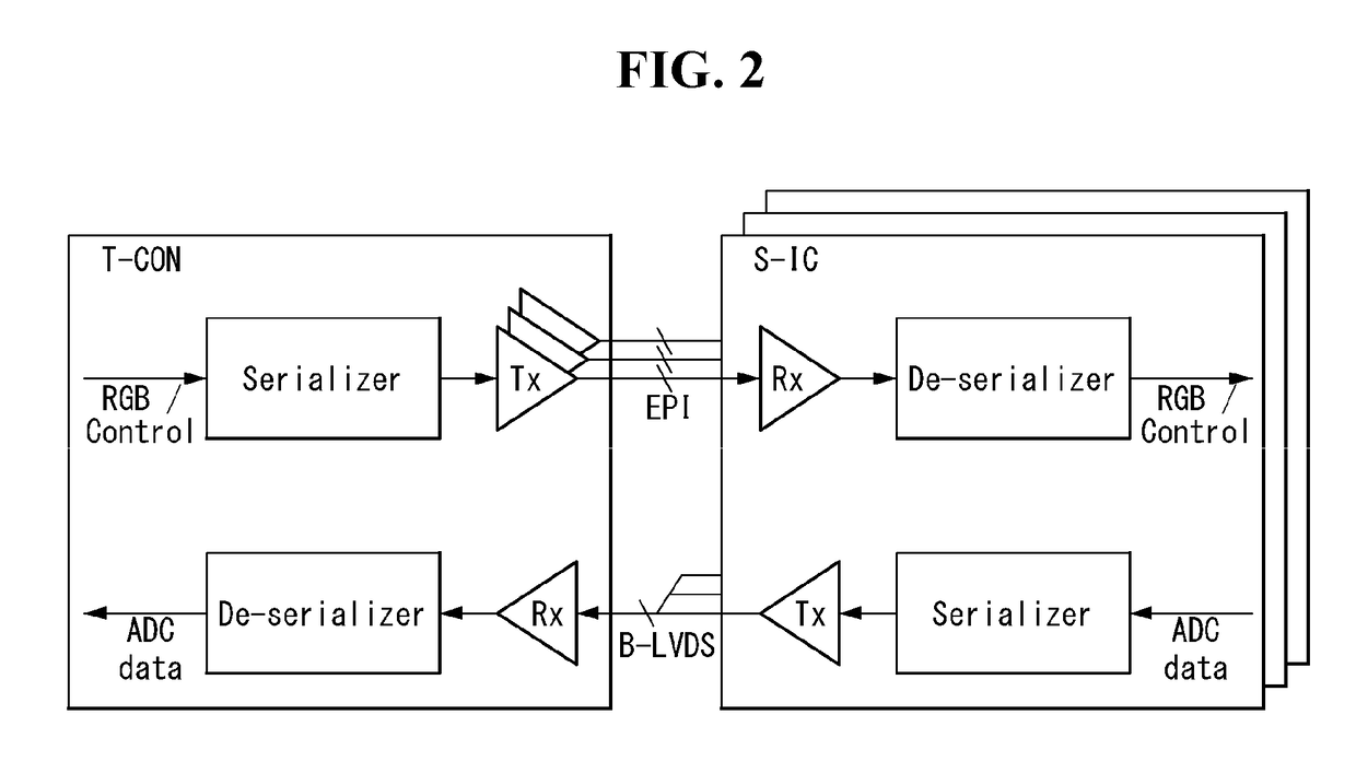
The present invention aims to provide a display device with a simple interface that connects a panel and a timing controller. It also improves the speed of data transmission between the panel and the timing controller to allow for real-time sensing of the driving characteristics of more pixels. By eliminating the need for a separate interface for sensing data transfer, the number of connections between the timing controller and the source drive IC is reduced, simplifying the overall connection structure. Overall, this invention simplifies the manufacturing process and improves operational efficiency of display devices.

Problems solved by technology

So, unless the characteristic deviations are compensated, it is difficult to realize desired quality for image.
An external compensation method senses the characteristic parameters of the driving TFTs of individual pixels and precisely corrects input data according to the sensing values, but has a disadvantage that it takes a long time for sensing.
On the other hand, an internal compensation method can compensate for the luminance deviation in real-time but has a disadvantage that a pixel structure is complicated and an aperture ratio is low.
Particularly, the interface for transmitting the digital sensing data is driven in a multi-drop manner, and a clock wiring pair is required separately from a signal wiring pair, so there are problems that the number of pads of the source drive IC is large and a transfer speed is slow.

Method used


Image

  • Display Device
  • Display Device
  • Display Device

Examples


Embodiment Construction

[0032]Hereinafter, embodiments of the present disclosure will be described in detail with reference to the accompanying drawings. Same reference numerals throughout the specification denote substantially identical components. In the following description, a detailed description of known functions and configurations incorporated herein will be omitted when it may make the subject matter of the present disclosure rather unclear.

[0033]A general display device includes a timing controller, a data driving circuit, a gate driving circuit, and a panel. The timing controller receives video data and a timing signal from a source, processes the data, and provides the processed data to the data driving circuit and the gate driving circuit as video signals and control signals. The data driving circuit and the gate driving circuit are connected directly to the pixels included in the panel through data lines and gate lines to display image through the pixels.

[0034]The source and the timing contro...


PUM


Abstract

The display device according to an embodiment of the present disclosure comprises a display panel; a source drive IC configured to provide data voltages to the pixels, convert signals indicating driving characteristics of the pixels into sensing data and output the sensing data; and a timing controller configured to transmit a control data packet and a video data packet to the source drive IC through first and second wire pairs and receive the sensing data from the source drive IC through the second wire pair, wherein the timing controller is configured to load lock information indicating whether a clock extracted from a signal provided from the source drive IC through the second wire pair is locked or not into the control data packet and provide the control data packet to the source drive IC through the first wire pair, when receiving data from the source drive IC.

Description

CROSS-REFERENCE TO RELATED APPLICATIONS[0001]This application claims the benefit of priority under 35 U.S.C. § 119(a) of Republic of Korea Patent Application No. 10-2016-0142751 filed on Oct. 31, 2016, which is incorporated by reference herein in its entirety.BACKGROUNDField of Technology[0002]The present disclosure relates to an interface structure for exchanging data between a controller and a panel in a display device.Discussion of the Related Art[0003]An active matrix type organic light emitting display covers an organic light emitting diode (hereinafter, referred to as “OLED”) which emits light by itself, and has advantages of a fast response speed, high light emitting efficiency, high brightness, and a wide viewing angle.[0004]An organic light emitting display device arranges pixels each including an OLED and a driving TFT (Thin Film Transistor) in a matrix form, and adjusts the luminance of an image implemented in a pixel according to gradation of video data. The driving TFT ...

Claims


Application Information

Patent Timeline
IPC IPC(8): G09G3/20
CPCG09G3/2096G09G2310/08G09G2320/0233G09G2370/08G09G2330/02G09G2370/10G09G2320/043G09G3/3266G09G3/3275G09G3/3233G09G3/3225G09G5/008G09G2320/045G09G3/20G09G3/3688G09G2310/061G09G2300/0828
Inventor DO, OSUNGNOH, JUYOUNG
Owner LG DISPLAY CO LTD
Learn More