Power module and magnetic component thereof

a power module and magnetic component technology, applied in the direction of transformer/inductance magnetic core, printed circuit aspects, printed circuit non-printed electric components association, etc., can solve the problems of large footprint occupying much more space on the client circuit board, and longer power transmission trace, so as to reduce the entire volume of the power module, increase the power density, and high conversion efficiency

Active Publication Date: 2018-05-03
DELTA ELECTRONICS INC
View PDF10 Cites 24 Cited by
  • Summary
  • Abstract
  • Description
  • Claims
  • Application Information

AI Technical Summary

Benefits of technology

[0006]An object of the present invention is to provide a power module and a magnetic component thereof. The magnetic component includes a window passing through the top surface and the bottom surface. By stacking the magnetic component and the power device of the power module together, the vertical projection of the top surface and the bottom surface of the magnetic core

Problems solved by technology

In a conventional power module integration, there are various power devices and magnetic components placed horizontally on a circuit substrate, so that it makes the footprint of the power module large and occupies much more space on the client circuit board.
In addition, its power transmission

Method used


Image

  • Power module and magnetic component thereof
  • Power module and magnetic component thereof
  • Power module and magnetic component thereof

Examples


Embodiment Construction

[0074]The present invention will now be described more specifically with reference to the following embodiments. It is to be noted that the following descriptions of preferred embodiments of this invention are presented herein for purpose of illustration and description only. It is not intended to be exhaustive or to be limited to the precise form disclosed.

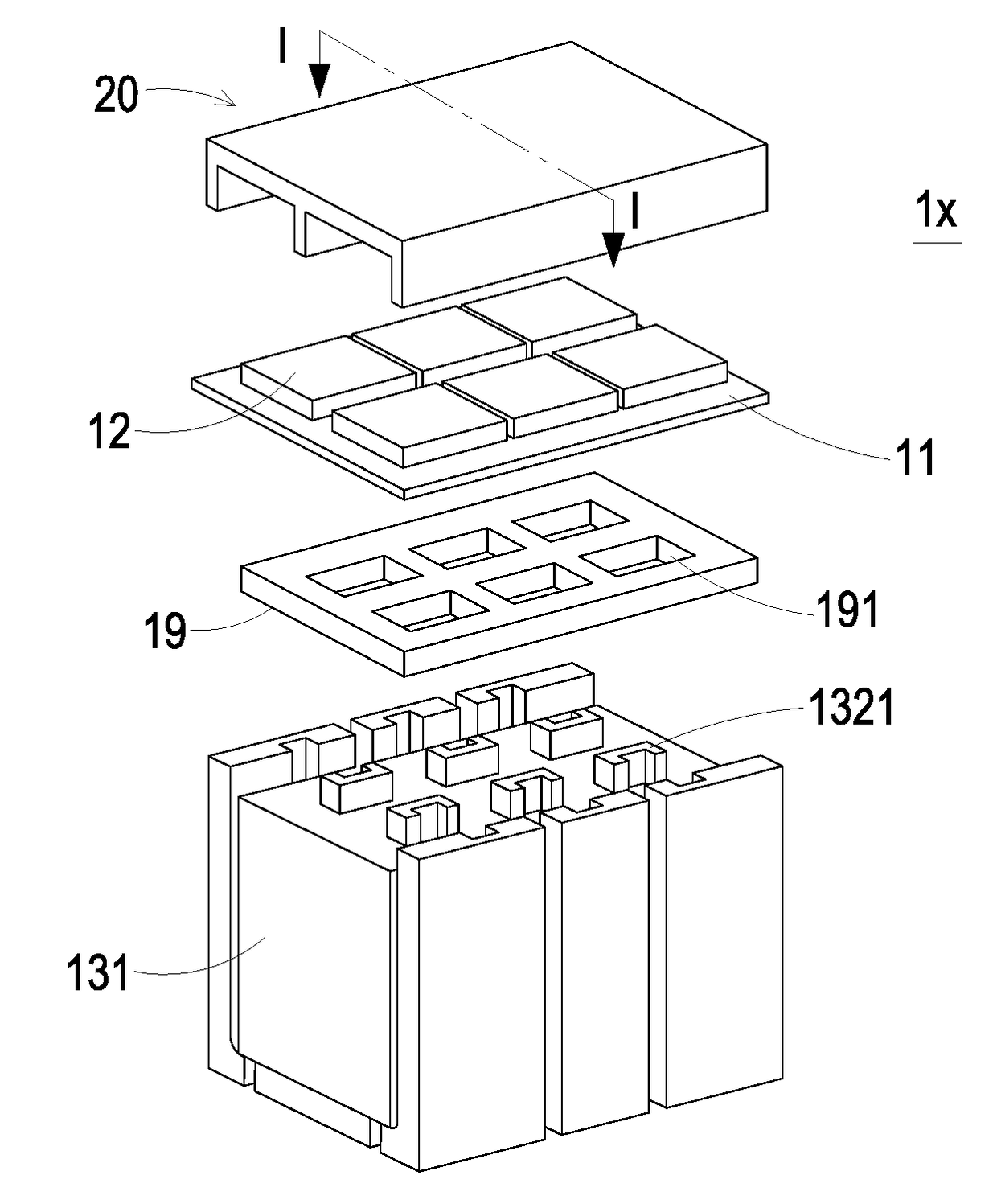
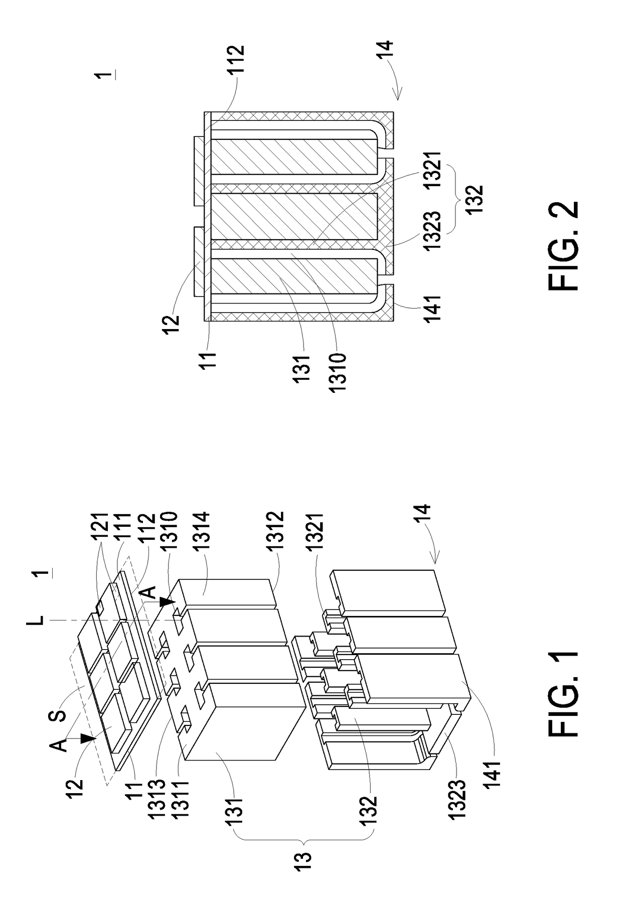
[0075]FIG. 1 is a 3D view illustrating a power module according to a first preferred embodiment of the present invention. FIG. 2 is a cross sectional view illustrating the assembled power module and taken along AA line of FIG. 1. As shown in FIG. 1, the power module 1 includes at least one first substrate 11, a power device 12 and a magnetic component 13. The first substrate 11, the power device 12 and the magnetic component 13 are stacked together, and a vertical projection of the magnetic component 13 is at least partially overlapping with the power device 12. In the embodiment, the magnetic component 13 includes a magnetic cor...


PUM


Abstract

A power module including a power device and a magnetic component is provided. The magnetic component is stacked with the power device and a vertical projection of the magnetic component is at least partially overlapping with the power device. The magnetic component includes a magnetic core and a winding set. The magnetic core includes a first surface, a second surface and at least one window. The window is located between the first surface and the second surface, and includes a passing-through axis vertical to a surface of the power device, where at least one leading pin or pad is disposed on the surface of the power device. The winding set includes at least one winding portion. The winding portion passes through the window and electrically connected to the power device. Each winding set and the magnetic core are configured to form an inductor, and the winding set is preformed.

Description

FIELD OF THE INVENTION[0001]The present invention relates to a power module, and more particularly to a power module having high power density and a magnetic component thereof.BACKGROUND OF THE INVENTION[0002]In a conventional power module integration, there are various power devices and magnetic components placed horizontally on a circuit substrate, so that it makes the footprint of the power module large and occupies much more space on the client circuit board. In addition, its power transmission trace is longer, and the longer trace causes greater impedance. Consequently, the efficiency of the power module is influenced.[0003]Some power modules include the power devices and the magnetic components stacked together on a circuit substrate, but the window-passing direction of the magnetic components is still parallel to the circuit substrate. The connection traces between the windings of the magnetic components and the power devices are still long and the power loss can't be reduced...

Claims


Application Information

Patent Timeline
IPC IPC(8): H01F27/29H05K1/18H01F27/24H05K1/11
CPCH01F27/29H05K1/185H05K1/181H01F27/24H05K1/115H05K1/111H05K2201/1003H01F27/2847H01F27/306H01L27/02
Inventor JI, PENGKAIZHOU, JINPINGHONG, SHOUYUWANG, TAOZENG, JIANHONGXIN, ZHANGNAN
Owner DELTA ELECTRONICS INC
Why Eureka
Try Eureka