Spin-orbit torque magnetization rotational element

Active Publication Date: 2018-05-03
TDK CORPARATION
View PDF2 Cites 16 Cited by
  • Summary
  • Abstract
  • Description
  • Claims
  • Application Information

AI Technical Summary

Benefits of technology

[0028]According to the present invention, it is possible to provide a spin-orbit torque magnetization

Problems solved by technology

This is because it is difficult to impart sufficient tor

Method used


Image

  • Spin-orbit torque magnetization rotational element
  • Spin-orbit torque magnetization rotational element
  • Spin-orbit torque magnetization rotational element

Examples


examples

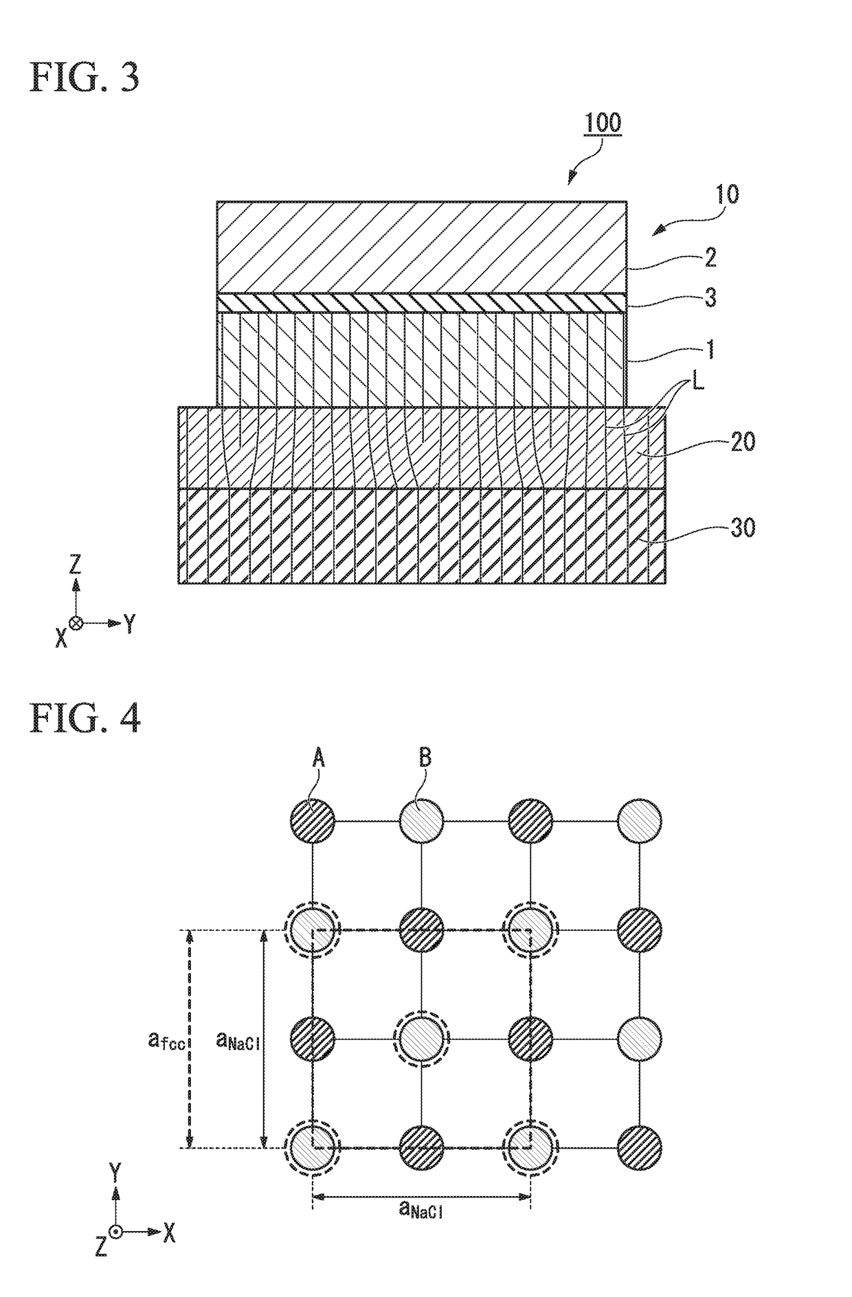
(Calculation of Degree of Lattice Mismatching)

[0138]The material used for the spin-orbit torque wiring and the material used for the interfacial distortion supply layer were respectively changed to determine the degree of lattice mismatching for each material.

[0139]The lattice constant of each material was obtained by actual measurement and calculation. For the calculation, it was obtained using the site of “AtomWork” (Search on October 13, Heisei 8, URL: http: / / crystdb.nims.go.jp / ) managed by National Institute for Materials Science and Technology, Japan. Note that the site of “Atom Work” is prepared based on Inorganic Materials Database for Exploring the Nature of Material. Jpn. J. Appl. Phys. 50 (2011) 11 RH 02 (Yibin Xu, Masayoshi Yamazaki, and Pierre Villars).

[0140]First, a material having a NaCl structure was selected as an interfacial distortion supply layer. The spin orbital torque wiring for this was changed, and the degree of lattice mismatching of each was obtained based...


PUM


Abstract

A spin-orbit torque magnetization rotational element includes: a ferromagnetic metal layer, a magnetization direction of which is configured to be changed; a spin-orbit torque wiring bonded to the ferromagnetic metal layer; and an interfacial distortion supply layer bonded to a surface of the spin-orbit torque wiring on a side opposite to the ferromagnetic metal layer.

Description

BACKGROUND OF THE INVENTIONTechnical Field[0001]The present invention relates to a spin-orbit torque magnetization rotational element and a magnetic memory.[0002]The present invention relates to a magnetoresistance effect element. Priority is claimed on Japanese Patent Application No. 2016-210532, filed Oct. 27, 2016, the content of which is incorporated herein by reference.Description of Related Art[0003]A giant magnetoresistive (GMR) element including a multilayered film of a ferromagnetic layer and a nonmagnetic layer and a tunneling magnetoresistance (TMR) element using an insulating layer (a tunnel barrier layer, a barrier layer) in a nonmagnetic layer are known. Generally, the TMR element has a higher element resistance than the GMR element. However, the TMR element has a larger MR ratio than the GMR element. Therefore, TMR elements are of interest as elements for magnetic sensors, high frequency components, magnetic heads and nonvolatile random access memories (MRAM).[0004]Th...

Claims


Application Information

Patent Timeline
IPC IPC(8): H01L43/08H01L43/04H01L43/06H01L43/10H01F10/32
CPCH01L43/08H01L43/04H01L43/06H01L43/10H01F10/324G11C11/161H10N50/85H10N50/10H01F10/30H01F10/329H10N50/80H10N52/00H10N52/80
Inventor SHIOKAWA, YOHEISASAKI, TOMOYUKIOIKAWA, TOHRU
Owner TDK CORPARATION
Why Eureka
Try Eureka