Charging system and charging method for terminal and power adapter

a charging system and terminal technology, applied in the direction of several simultaneous battery arrangements, process and machine control, etc., can solve the problems of increasing the size of the power adapter, the mobile terminal consumes a large amount of power, and the battery needs to be charged frequently, so as to reduce the probability of arcing and the force of contact at the charging interface, the effect of reducing the probability of arcing and the effect of reducing the contact for

Active Publication Date: 2018-05-03
GUANGDONG OPPO MOBILE TELECOMM CORP LTD
View PDF0 Cites 9 Cited by
  • Summary
  • Abstract
  • Description
  • Claims
  • Application Information

AI Technical Summary

Benefits of technology

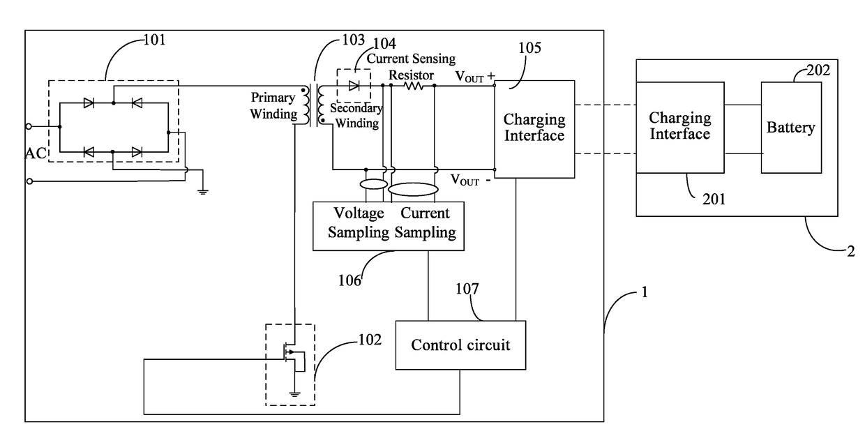
[0007]With the power of a power adapter becomes higher, the battery tends to polarize and the resistance tends to become larger when the power adapter charges the battery of the mobile terminal; the battery temperature thus rises to reduce the service life of the battery. As a result, the reliability and safety of the battery are affected.
[0008]In addition, when an AC power supplies power, most of the equipment cannot operate by directly using the AC power. The reason is that an AC power, such as 220V / 50 Hz mains, outputs power intermittently, and in order not to be “intermittent”, electrolytic capacitors need to be used for energy storage. When the power is at the wave trough, the power supply is maintained stably by continuously relying on the energy storage of electrolytic capacitors. Therefore, when a mobile terminal is charged by an AC power supply through a power adapter, the AC power, such as 220V AC power, provided by the AC power supply is first converted into a stable DC power be supplied to the mobile terminal. However, the power adapter charges the battery of the mobile terminal, thus indirectly supplying power to the mobile terminal. The continuity of power supply can be ensured by the battery. As such, the power adapter does not need to continuously output a stable DC power when charging the battery.
[0009]Therefore, one objective of the present disclosure is to provide a charging system for a terminal. With the charging system, voltage with a pulsating waveform outputted by a power adapter is directly applied to a battery of the terminal, thereby miniaturizing the power adapter, lowering the cost of the power adapter, and increasing the lifetime of the battery. Besides, two current sampling modes are alternatively switched to sample the current, which ensures the sensing function with the compatibility between sensing precision and dynamic range and expands the scope of the applications.
[0012]According to the embodiment of the present disclosure, the charging system for the terminal controls the power adapter to output the voltage with the third pulsating waveform, and directly applies the voltage with the third pulsating waveform output from the power adapter to the battery in the terminal, so that the fast charging of the battery directly by the output voltage / current that is pulsating can be achieved. A magnitude of the output voltage / current that is pulsating changes periodically. As compared with the disclosures of charging with constant voltage and constant current in the related art, the lithium precipitation phenomenon of the lithium battery can be reduced. The service life of the battery can be improved. In addition, the probability of arcing and the force of the contact at the charging interface can further be reduced to improve the life of the charging interface. It is also advantageous in reducing the polarization effect of the battery, improving the charging speed, reducing the battery heat so as to ensure the safety and reliability when the terminal is charged. Additionally, because the power adapter outputs the voltage with the pulsating waveform, there is no necessity to dispose electrolytic capacitors in the power supply adapter. Not only can the power adapter be simplified and miniaturized, but the cost can also be greatly reduced. Additionally, two current sampling modes are alternatively switched to sample the current, which ensures the sensing function with the compatibility between sensing precision and dynamic range and expands the scope of the applications.
[0014]According to the embodiment of the present disclosure, the power adapter outputs the voltage with the third pulsating waveform through the first charging interface, and directly applies the voltage with the third pulsating waveform output from the power adapter to the battery through the second charging interface in the terminal, so that the fast charging of the battery directly by the output voltage / current that is pulsating can be achieved. A magnitude of the output voltage / current that is pulsating changes periodically. As compared with the disclosures of charging with constant voltage and constant current in the related art, the lithium precipitation phenomenon of the lithium battery can be reduced. The service life of the battery can be improved. In addition, the probability of arcing and the force of the contact at the charging interface can further be reduced to improve the life of the charging interface. It is also advantageous in reducing the polarization effect of the battery, improving the charging speed, reducing the battery heat so as to ensure the safety and reliability when the terminal is charged. Additionally, because the power adapter outputs the voltage with the pulsating waveform, there is no necessity to dispose electrolytic capacitors in the power supply adapter. Not only can the power adapter simplified and miniaturized, but the cost can also be greatly reduced. Additionally, two current sampling modes are alternatively switched to sample the current, which ensures the sensing function with the compatibility between sensing precision and dynamic range and expands the scope of the applications.
[0016]According to the charging method provided in the embodiment of the present disclosure, the voltage with the third pulsating waveform is outputted by controlling the power adapter, and the voltage with the third pulsating waveform output from the power adapter is directly applied to the battery of the terminal, so that the fast charging of the battery directly by the output voltage / current that is pulsating can be achieved. A magnitude of the output voltage / current that is pulsating changes periodically. As compared with the disclosures of charging with constant voltage and constant current in the related art, the lithium precipitation phenomenon of the lithium battery can be reduced. The service life of the battery can be improved. In addition, the probability of arcing and the force of the contact at the charging interface can further be reduced to improve the life of the charging interface. It is also advantageous in reducing the polarization effect of the battery, improving the charging speed, reducing the battery heat so as to ensure the safety and reliability when the terminal is charged. Additionally, because the power adapter outputs the voltage with the pulsating waveform, there is no necessity to dispose electrolytic capacitors in the power supply adapter. Not only can the power adapter simplified and miniaturized, but the cost can also be greatly reduced. Additionally, two current sampling modes are alternatively switched to sample the current, which ensures the sensing function with the compatibility between sensing precision and dynamic range and expands the scope of the applications.

Problems solved by technology

However, the mobile terminals consume a great amount of power so that they need to be charged frequently.
This causes size of the power adapters to increase as well as manufacturing difficulty of the adapters to also increase.
However, when the mobile terminal is charged with small current outputted by the power adapter, a wider dynamic range of the operational amplifier by using a smaller current sensing resistor or selecting a lower amplification of the operational amplifier) may result in inaccuracy of detection of the small current because of the characteristic of the operational amplifier, which further affects the application of the power adapter.
With the power of a power adapter becomes higher, the battery tends to polarize and the resistance tends to become larger when the power adapter charges the battery of the mobile terminal; the battery temperature thus rises to reduce the service life of the battery.
As a result, the reliability and safety of the battery are affected.
In addition, when an AC power supplies power, most of the equipment cannot operate by directly using the AC power.

Method used


Image

  • Charging system and charging method for terminal and power adapter
  • Charging system and charging method for terminal and power adapter
  • Charging system and charging method for terminal and power adapter

Examples


Embodiment Construction

[0038]Embodiments of the present application are illustrated in detail in the accompanying drawings, in which like or similar reference numerals refer to like or similar elements or elements having the same or similar functions throughout the specification. The embodiments described below with reference to the accompanying drawings are exemplary and are intended to be illustrative of the present application, and are not to be construed as limiting the scope of the present application.

[0039]Before a charging system and a charging method for a terminal and a power adapter according to the embodiments of the present disclosure are provided, description of a power adapter for charging a chargeable device (e.g. a terminal), that is, an “associated adapter” as called in the following, in the relevant technology is first described.

[0040]The associated adapter constantly maintains an output voltage when the associated adapter operates in a constant voltage mode, such as 5V, 9V, 12V, or 20V,...


PUM


Abstract

A charging system, a charge method, and a power adapter are provided. The charging system includes a battery, a first rectifying circuit, a switch circuit, a transformer, a second rectifying circuit, a sampling circuit, and a control circuit. The control circuit outputs a control signal to the switch circuit, and regulates a duty cycle of the control signal according to the current sampling value so that the voltage with the third pulsating waveform satisfies a requirement of charging the battery.

Description

BACKGROUND1. Field of Disclosure[0001]The present disclosure relates to a terminal device technology, more particularly, to a charging system for a terminal, a charging method for the terminal, and a power adapter.2. Description of Related Art[0002]Currently, mobile terminals (such as a smart phone) are increasingly popular with consumers. However, the mobile terminals consume a great amount of power so that they need to be charged frequently.[0003]The mobile terminals are usually charged through power adapters. A power adapter generally includes a primary rectifier circuit, a primary filter circuit, a transformer, a secondary rectifier circuit, a secondary filter circuit, and a control circuit, etc. The power adapter converts input 220V alternating current (AC) power into a stable low-voltage direct current (DC) power (such as 5V) suitable for the mobile terminal, so as to provide power to a power management device and a battery of the mobile terminal, thus charging the mobile term...

Claims


Application Information

Patent Timeline
Patent Type & Authority Applications(United States)
IPC IPC(8): H02J7/04H02M3/335H02M1/08H02J7/02H02J7/06
CPCH02J7/045H02M3/33507H02M1/08H02J7/041H02J7/022H02J7/06H02J2007/0096H02M2001/0009H02J7/008H02M3/335H02J7/00711H02J7/0071H02J7/00034H02J7/02H02J2207/20Y02E60/10H02J7/04H02J7/007182H02M7/04H02M1/44H02J7/00H02J7/00043H02J7/00714H02J7/00036H02J7/00712H01M10/4257H02J7/0031H02M3/33592H01M10/0525H02J7/0029H02J7/007188H02M3/33569H02J7/007H02M1/0009H02M7/217H02J2207/10H02J7/0049H02J7/2434H02M7/06H01M10/425H02J7/00304H02J7/007192H02M3/33576H01M10/44H02J7/0042H02M5/04G01R31/3842H02J7/0025H02M3/33523H01M2010/4271H02J7/0047
Inventor TIAN, CHENZHANG, JIALIANG
Owner GUANGDONG OPPO MOBILE TELECOMM CORP LTD
Why Eureka
Try Eureka