Eureka AIR delivers breakthrough ideas for toughest innovation challenges, trusted by R&D personnel around the world.

Dynamic bone anchor and method of manufacturing the same

a bone anchor and dynamic technology, applied in the field of dynamic bone anchors, can solve the problems of high material elasticity, and achieve the effect of increasing strength

Active Publication Date: 2018-05-10
BIEDERMANN TECH GMBH & CO KG
View PDF0 Cites 0 Cited by
  • Summary
  • Abstract
  • Description
  • Claims
  • Application Information

AI Technical Summary

Benefits of technology

[0007]Superelasticity, sometimes called pseudoelasticity, involves the creation of stress-induced martensite which simultaneously undergoes strain when it is formed to release the applied stress. When the applied stress is released, the thermally unstable martensite reverts to austenite, and the strain returns to zero. This process results in high elasticity in the material.
[0008]Due to the superelastic behavior of the core member, the degree of possible movement of the core member relative to the anchor member is increased compared to materials without superelasticity. The plateau in the stress-strain diagram of a Ni—Ti based shaped memory alloy shows a substantially constant stress exhibited when stress-induced martensite starts forming. This provides for an overload protection, for example during the screwing in of the dynamic bone anchor. In addition, the entire dynamic bone anchor can be designed with a relatively short length, compared to similar bone anchors made of other materials.
[0010]The dynamic bone anchor can be provided as a modular system, wherein a core member can be selectively combined with anchor members of different shapes, lengths, or other properties, for example different thread types, barbs etc. This has the advantage that the characteristics of the core member that substantially define the dynamic characteristics of the whole entire dynamic bone anchor, can be utilized in different combinations of core members with anchor members.
[0012]With the method of manufacturing the bone anchor that makes use of the shape memory effect of the Ni—Ti shape memory alloy of the core member, the core member can be easily connected to anchor members of different length or other different properties. A resulting press-fit connection between the core member and the anchor member has a higher strength than conventionally generated press-fit connections.

Problems solved by technology

This process results in high elasticity in the material.

Method used


Image

  • Dynamic bone anchor and method of manufacturing the same
  • Dynamic bone anchor and method of manufacturing the same
  • Dynamic bone anchor and method of manufacturing the same

Examples


Embodiment Construction

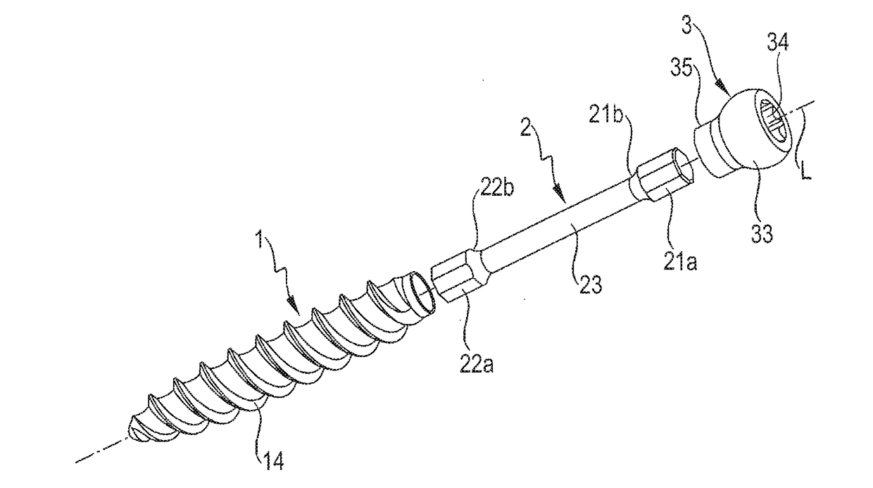
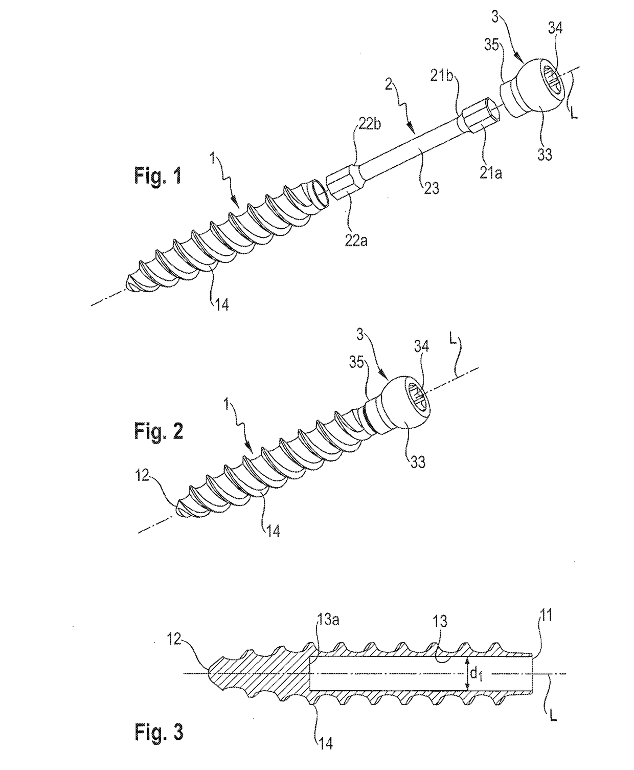
[0036]As shown in FIGS. 1 and 2, a dynamic bone anchor according to a first embodiment, comprises an anchor member 1 in the form of a screw member, a core member 2 and a head 3. The core member 2 can be inserted into the anchor member 1 and connected thereto, and the head 3 can be connected to the core member 2.

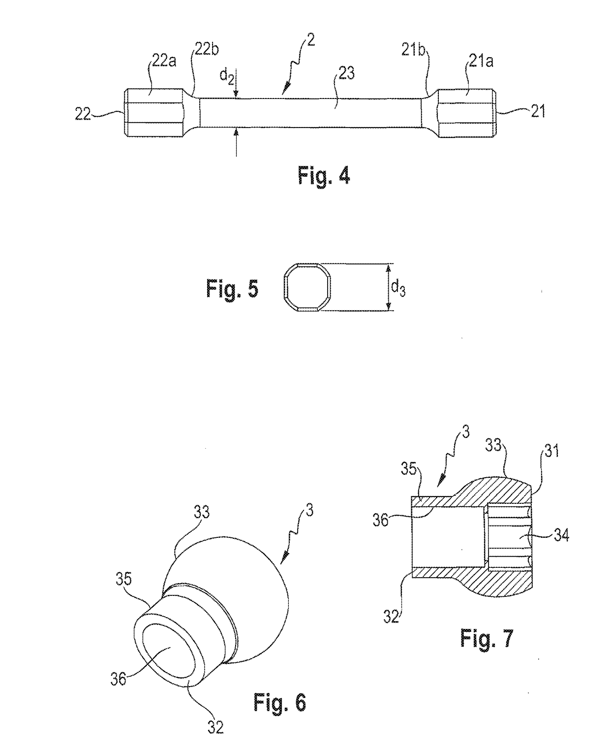
[0037]As further shown in FIG. 3, the anchor member 1 comprises a first end 11, an opposite second end 12, and a longitudinal axis L extending through the first end 11 and the second end 12. The longitudinal axis L forms the central axis of the bone anchor. Adjacent to the first end 11, the anchor member 1 comprises a tubular section 13 with an opening at the first end 11. The tubular section 13 extends a distance toward the second end 12, and has an inner diameter d1 and a length adapted to accommodate a portion of the core member 2 as described below. An end surface 13a of the tubular section provides a stop for the insertion of the core member 2. The second end 12 of the a...


PUM

PropertyMeasurementUnit
temperature sensitive propertyaaaaaaaaaa
temperatureaaaaaaaaaa
superelasticaaaaaaaaaa

Abstract

A dynamic bone anchor includes an anchor member having first and second ends and a tubular section between the ends, a longitudinal axis extending from the first to second end, an outer surface, and a bone engagement structure for engaging a bone on at least a portion of the outer surface; and a longitudinal core member having a first portion and a second portion configured to be received in the tubular section and to connected to the anchor member, with the first portion configured to be spaced apart from the anchor member and movable with respect to it. The core member is made at least partially of a nickel-titanium (Ni—Ti) based shape memory alloy such that its shape after transitioning from a martensitic to austenitic phase is configured to result in a press-fit connection between the second portion and the anchor member with the second portion in the austenitic phase.

Description

CROSS-REFERENCE TO RELATED APPLICATION[0001]This application is a continuation of U.S. patent application Ser. No. 14 / 098,434, filed Dec. 5, 2013, which claims priority to and the benefit of U.S. Provisional Application No. 61 / 733,769, filed Dec. 5, 2012, in the U.S. Patent and Trademark Office, the entire content of which is incorporated herein by reference; and claims priority from European Patent Application EP 12 195 758.3, filed Dec. 5, 2012, the entire content of which is incorporated herein by reference.BACKGROUND1. Field[0002]The invention relates to a dynamic bone anchor and a method of manufacturing a dynamic bone anchor. The dynamic bone anchor comprises an anchor member for anchoring to a bone or a vertebra, and a longitudinal core member provided in the anchor member, a portion of which is movable with respect to the anchor member. The core member is made, at least partially, of a material comprising a nickel-titanium (Ni—Ti) based shape memory alloy having superelastic...

Claims


Application Information

Patent Timeline
Patent Type & Authority Applications(United States)
IPC IPC(8): A61B17/86A61B17/00A61B17/70
CPCA61B2017/00862A61B17/7035Y10T29/49826A61B17/8685A61B17/866A61B17/8625A61B17/86A61B2017/00867
Inventor BIEDERMANN, LUTZMATTHIS, WILFRIED
Owner BIEDERMANN TECH GMBH & CO KG
Why Eureka
Eureka Blog
Learn More