Self Charger for Electric Vehicles

a self-charging and electric vehicle technology, applied in the direction of electric propulsion mounting, machines/engines, transportation and packaging, etc., can solve the problem of limited driving distance of electric vehicles, and achieve the effect of reducing carbon footprint, longer travel times, and reducing fossil fuel consumption

Active Publication Date: 2018-05-10
KIM CHUIL PETER
View PDF9 Cites 7 Cited by
  • Summary
  • Abstract
  • Description
  • Claims
  • Application Information

AI Technical Summary

Benefits of technology

[0003]Harnessing wind energy within an automobile with the wind powered system of the invention will lead to longer travel times by non-combustible engines. Fossil fuels will be lessened which will lead to a smaller carbon footprint on Earth. On average, electric vehicles will travel anywhere from 40-100 miles on a single charge. This is in particular reference to strictly electric vehicles. If these same vehicles could also harness wind energy by the wind powered system of the invention to sustain a constant drive, it enables the vehicles to utilize two power sources at once.
[0004]An electric vehicle is propelled by electric motors using energy stored in a battery or similar device, but the electric vehicle is limited in driving distances as it is dependent on the time it has been charged and the amount of charge it has received. The wind powered system of the invention enables to further optimize the energy used by electric vehicles and to provide an additional source of energy to decrease battery depletion.

Problems solved by technology

An electric vehicle is propelled by electric motors using energy stored in a battery or similar device, but the electric vehicle is limited in driving distances as it is dependent on the time it has been charged and the amount of charge it has received.

Method used


Image

  • Self Charger for Electric Vehicles
  • Self Charger for Electric Vehicles
  • Self Charger for Electric Vehicles

Examples


Embodiment Construction

[0010]A semiconductor device according to the present invention will be described below in detail with reference to the accompanying drawings.

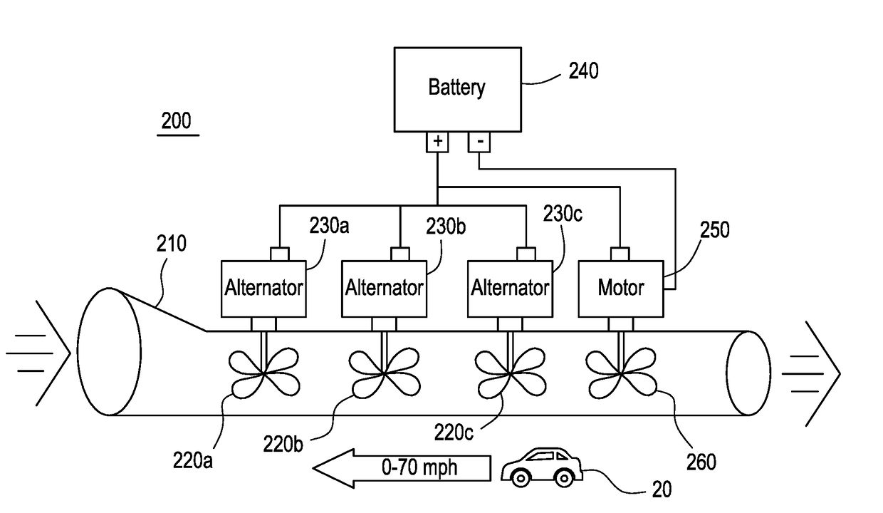
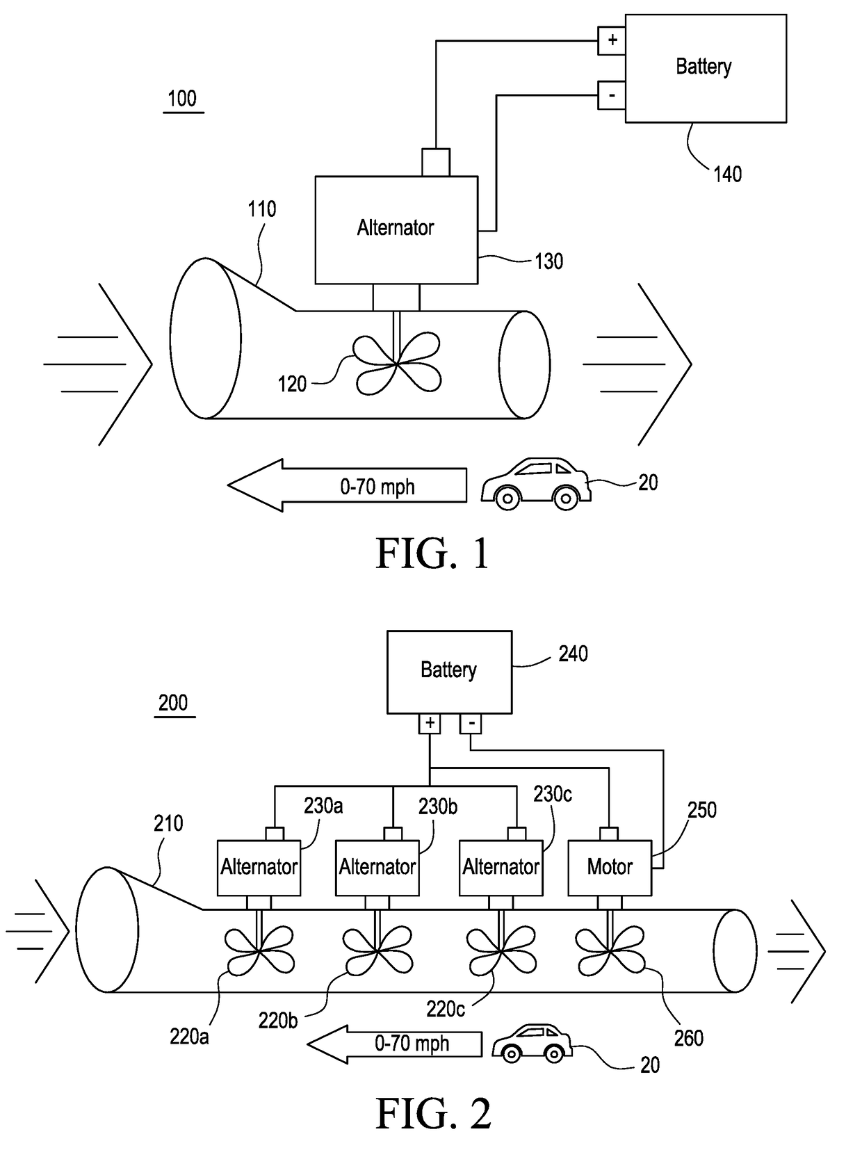
[0011]FIG. 1 illustrates a wind powered system 100 located inside a body of a car 20. Whether parked or in motion, the car 20 captures wind which passes through a wind tunnel 110. Inside the wind tunnel 110 is a rotary fan 120 that is connected to and feeds an alternator 130, which charges a battery 140 and powers an electrical system. The amount of power or electricity generated by the wind powered system 100 will be low and is not sufficient to power the car independently. However, in motor vehicles fueled by gasoline or diesel, this wind powered system can provide supplementary power for, among other things, lighting, audio system, and air conditioner of vehicles. This solution can ultimately decrease the overall battery depletion and reduce the amount of fuel consumed by the vehicles. FIG. 1 is the basic principle behind the consolidated d...


PUM


Abstract

Provided is a wind powered system which provides electrical energy to a vehicle using wind flow through wind tunnels. The system includes a plurality of ducts or wind tunnels each of which accommodates a plurality of rotary fans which are connected to a corresponding one of a plurality of alternators. A pulling fan and a motor connected to the pulling fan are provided to pull and move the wind throughout the ducts.

Description

BACKGROUND OF THE INVENTION[0001]The present invention relates to a self-charger or wind powered system for vehicles.SUMMARY OF THE INVENTION[0002]According to one aspect of the invention, a self-charger or a wind powered system for an electric vehicle is provided with ducts, rotary fans and alternators. The vehicle, equipped with the wind powered system of the invention, may utilize the wind power collected through the ducts while the vehicle is parked or in motion. Wind power is received by the rotary fans connected to alternators which supply energy to the car battery. The wind powered system of the invention focuses on a consolidation of fans, alternators and motors to harness the wind power and transform it into energy that can be consumed by an automobile.[0003]Harnessing wind energy within an automobile with the wind powered system of the invention will lead to longer travel times by non-combustible engines. Fossil fuels will be lessened which will lead to a smaller carbon fo...

Claims


Application Information

Patent Timeline
Patent Type & Authority Applications(United States)
IPC IPC(8): B60L8/00F03D9/25B60K1/02
CPCB60L8/006F03D9/25Y02T10/7083Y02E10/725B60K1/02F05B2240/941F03D9/32Y02E10/72Y02E10/728Y02T10/7072
Inventor KIM, CHUIL PETER
Owner KIM CHUIL PETER
Why Eureka
Try Eureka