
Method of manufacturing battery separator using treatment of modifying surface

a technology of modifying surface and battery cell, which is applied in the direction of cell components, final product manufacturing, sustainable manufacturing/processing, etc., can solve the problems of unfavorable environmental protection, reduced price competitiveness, and uniform pores, and achieve the effect of satisfying air permeability and puncture strength properties, improving thermal shrinkage and wettability of the battery cell

Inactive Publication Date: 2018-05-10
UPEX CHEM
View PDF2 Cites 2 Cited by
  • Summary
  • Abstract
  • Description
  • Claims
  • Application Information

AI Technical Summary

Benefits of technology

The present invention provides a method of producing a battery separator using surface modification treatment. The method produces the battery separator using a dry process that satisfies air permeability and puncture strength properties required in the battery separator. Additionally, the method improves thermal shrinkage and wettability of the battery cell, which is appropriate for high-capacity and compact batteries. The method involves controlling a current between 0.3 A and 1.8 A based on the gap between electrodes, using a corona discharge treatment. This treatment increases the pore size of the film, resulting in reduced thermal shrinkage and increased wettability compared to a film not subjected to the corona discharge treatment.

Problems solved by technology

The wet process is not environmentally friendly due to the use of an extraction solvent, and uses a complicated production process that reduces price competitiveness.
Since the separator produced by the method of adding inorganic materials has non-uniform pores and unstable quality such as reduced strength, the method of producing a separator by controlling crystal structures is frequently used.
If the wettability of the electrolyte is not good, many problems may arise in that the electrolyte overflows during injection, or remains on the top, or is not uniformly distributed in the battery cell, or contaminates equipment in subsequent processes.
However, a method that improves the thermal shrinkage and wettability of a separator while satisfying the air permeability and puncture strength properties of the separator has not yet been reported.

Method used


Image

  • Method of manufacturing battery separator using treatment of modifying surface
  • Method of manufacturing battery separator using treatment of modifying surface
  • Method of manufacturing battery separator using treatment of modifying surface

Examples


first embodiment

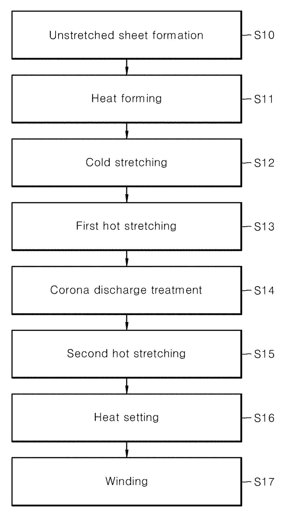
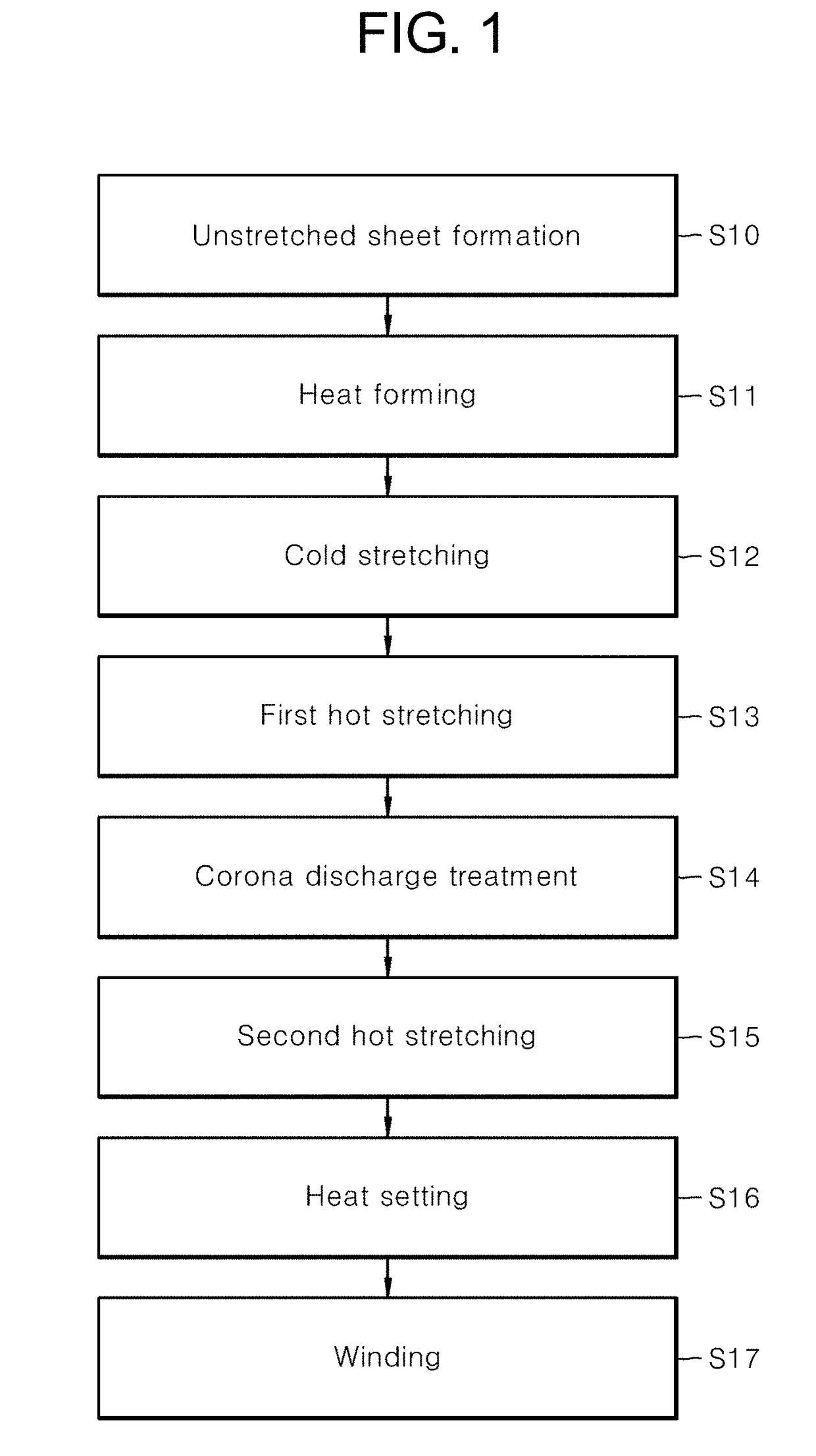
[0024]FIG. 1 is a flow chart showing a method for producing a battery separator according to a first embodiment of the present invention.

[0025]As shown in FIG. 1, in the first embodiment of the present invention, a polymer resin is first extruded to form an unstretched sheet (S10). Herein, the polymer resin is preferably semicrystalline, and may be, for example, a polymer compound selected from the group consisting of polyolefin, polyfluorocarbon, polyamide, polyester, polyacetal, polysulfide, polyvinyl alcohol, copolymers thereof, and combinations thereof. The polymer resin is preferably polyolefin resin, and example of the polyolefin resin include olefin homopolymers, including polypropylene, high-density polyethylene, low-density polyethylene, polybutene, polystyrene and the like, olefin copolymers, including ethylene-propylene copolymers, ethylene-butylene copolymers, propylene-butene copolymers and the like, and mixtures thereof.

[0026]When the polymer resin is extruded, various...

second embodiment

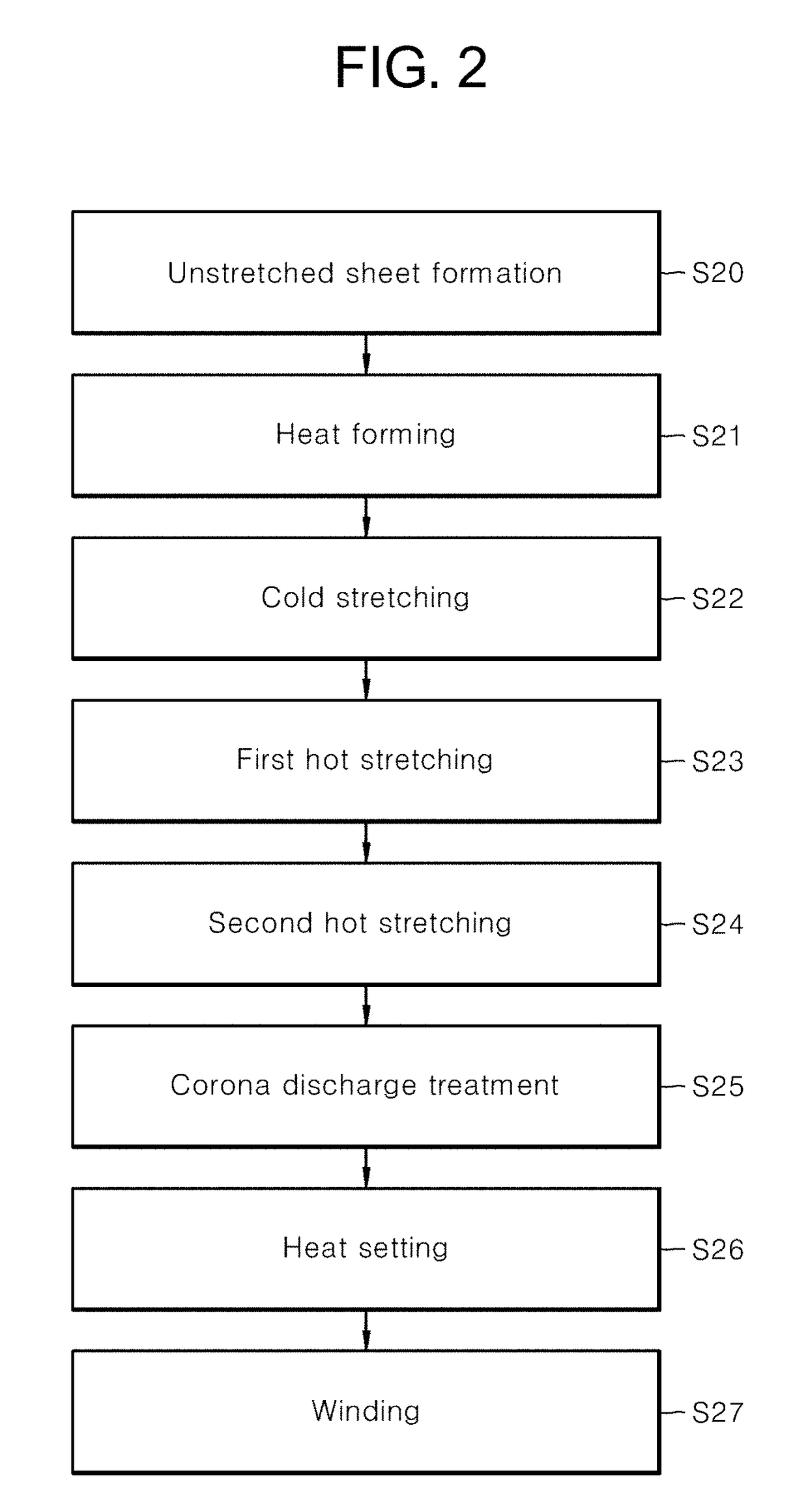
[0036]FIG. 2 is a flow chart showing a method for producing a battery separator according to a second embodiment of the present invention. The second embodiment is the same as the first embodiment, except that corona discharge treatment is performed after the completion of first hot stretching and second hot stretching. Accordingly, the detailed description of overlapping portions will be omitted below.

[0037]As shown in FIG. 2, in the second embodiment of the present invention, unstretched sheet formation (S20), heat forming (S21), cold stretching (S22), first hot stretching (S23), second hot stretching (S24), corona discharge treatment (S25), heat setting (S26) and winding (S27) steps are sequentially performed. As described above, the first hot stretching (S23) and the second hot stretching (S24) are preferably performed at a temperature between Tm−40° C. and Tm−10° C., wherein Tm is the melting temperature of the film. The degree of stretching in the second hot stretching is cont...

third embodiment

[0039]FIG. 3 is a flow chart showing a method for producing a battery separator according to a third embodiment of the present invention. The third embodiment is the same as the first embodiment, except that corona discharge treatment is performed after each of the first hot stretching and the second hot stretching. Accordingly, the detailed description of overlapping portions will be omitted below.

[0040]As shown in FIG. 3, in the third embodiment of the present invention, unstretched sheet formation (S30), heat forming (S31), cold stretching (S32), first hot stretching (S33), first corona discharge treatment (S34), second hot stretching (S35), second corona discharge treatment (S36), heat setting (S37) and winding (S38) steps are sequentially performed. As described above, the first hot stretching (S33) and the second hot stretching (S35) are preferably performed at a temperature between Tm−40° C. and Tm−10° C., wherein Tm is the melting temperature of the film. The degree of stret...


PUM

PropertyMeasurementUnit
speedaaaaaaaaaa
currentaaaaaaaaaa
currentaaaaaaaaaa

Abstract

Provided is a method of producing a battery separator using surface modification treatment, which produces the battery separator by a dry process, satisfies air permeability and puncture strength properties required in the battery separator, and improves the thermal shrinkage and wettability of the battery cell, thereby appropriately responding to the trend for high-capacity and compact batteries. The method comprises: forming an unstretched sheet; subjecting the unstretched sheet to heat forming; cold-stretching the sheet subjected to the heat forming, thereby obtaining a cold-stretched film; hot-stretching the cold-stretched film by first hot stretching and second hot stretching; and heat-setting the film subjected to the second hot stretching, wherein corona discharge treatment is performed between the first hot stretching and the heat setting.

Description

BACKGROUND OF THE INVENTIONField of the Invention[0001]The present invention relates to a method for producing a battery separator, and more particularly to a method for producing a battery separator, which comprises subjecting a battery separator, produced by a dry process, to corona discharge treatment to improve the physical properties of the battery separator.Description of the Prior Art[0002]Battery separators are required to have good general physical properties such as mechanical strength and electrolyte permeability, and properties such as air permeability, puncture strength, wettability and the like are the important properties of the battery separators. Battery separators may be produced by various processes, and have different properties depending on the production processes. Processes for producing battery separators can be largely classified into a dry process and a wet process. The wet process is not environmentally friendly due to the use of an extraction solvent, and...

Claims


Application Information

Patent Timeline
Patent Type & Authority Applications(United States)
IPC IPC(8): H01M2/14H01M2/18B29C47/00B29C59/14H01M50/403H01M50/406H01M50/414H01M50/469
CPCH01M2/145H01M2/18B29C47/0057B29C59/14B29L2031/755B29K2105/04H01M50/403H01M50/406H01M50/414H01M50/469B29C71/0063B29C59/10B29C2071/022B29C48/07B29C48/0018Y02E60/10B29C55/02B29L2031/3468Y02P70/50
Inventor RYU, SU SUNKANG, MYOUNG GU
Owner UPEX CHEM
Learn More