In-Situ Passivation and Insulation Layer for a Flexible Thermal Protection System (FTPS)

a thermal protection system and in-situ passivation technology, applied in the field of in-situ passivation and insulation layer of flexible thermal protection system, can solve the problems of complex layups, non-flexible, and brittleness of pica and similar materials (e.g. avcoat), and achieve the effects of complex design, and reducing the number of layers

Active Publication Date: 2018-05-17
NAT INST AEROSPACE ASSOC +1
View PDF4 Cites 1 Cited by
  • Summary
  • Abstract
  • Description
  • Claims
  • Application Information

AI Technical Summary

Benefits of technology

[0006]One aspect of the present disclosure is a method of providing a thermal barrier. The method includes positioning a layer of material comprising boron nitride nanotubes (BNNT) adjacent at least a portion of a surface to be shielded from thermal energy, whereby, in use, at least a portion of a surface of the layer of material forms boron oxide or boron carbide, or boron oxide and boron carbide, to provide one or more of in-situ heat passivation and / or a gas barrier when the layer of material is exposed to a high temperature gas. The layer of material may comprise a mat, and the layer of material may comprise an elemental resource such as nitrogen and / or carbon particles that react with the BNNT of the mat when the layer of material is exposed to a high temperature gas or a thermal load of greater than about 300° C., greater than about 500° C., or greater than about 800° C. The elemental resource may be disposed in the BNNT adjacent a surface thereof whereby the elemental resource reacts with the BNNT to form a refractory material such as a ceramic. The layer of material may comprise a BNNT mat having a thickness of about 0.5 mm to about 20 mm, and the BNNT mat may have a density of about 0.15 g / cm3 to about 1.7 g / cm3, or from about 0.15 g / cm3 to about 2.52 g / cm3. The layer of material may be attached to a space vehicle to provide thermal shielding for atmospheric reentry. The layer of material may be utilized to form an inflatable structure that forms a thermal shield for atmospheric re-entry of space vehicles.

Problems solved by technology

PICA and similar materials (e.g. AVCOAT) are very brittle, not flexible, and the oxidation temperature is less than 450° C. in air.
This limits use of these materials to rigid structures used in non-extreme thermal conditions.
Prior FTPS layups that have been designed are complex, non-flexible, multi-layered systems.
Determining how the FTPS will behave during EDL becomes more complicated with each additional material layer.
Furthermore, existing FTPSs are difficult to adapt for various deployable space vehicles.

Method used


Image

  • In-Situ Passivation and Insulation Layer for a Flexible Thermal Protection System (FTPS)
  • In-Situ Passivation and Insulation Layer for a Flexible Thermal Protection System (FTPS)
  • In-Situ Passivation and Insulation Layer for a Flexible Thermal Protection System (FTPS)

Examples


Embodiment Construction

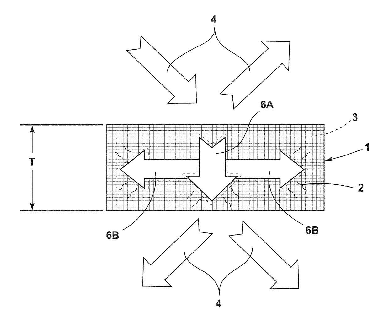
[0026]For purposes of description herein, the terms “upper,”“lower,”“right,”“left,”“rear,”“front,”“vertical,”“horizontal,” and derivatives thereof shall relate to the invention as oriented in FIG. 1. However, it is to be understood that the invention may assume various alternative orientations and step sequences, except where expressly specified to the contrary. It is also to be understood that the specific devices and processes illustrated in the attached drawings, and described in the following specification, are simply exemplary embodiments of the inventive concepts defined in the appended claims. Hence, specific dimensions and other physical characteristics relating to the embodiments disclosed herein are not to be considered as limiting, unless the claims expressly state otherwise.

[0027]One aspect of the present disclosure is a novel lightweight flexible BNNT mat (FIG. 1). As discussed in more detail below, BNNT mat 1 is an excellent flame retardant material and testing has dem...


PUM

PropertyMeasurementUnit
temperatureaaaaaaaaaa
thicknessaaaaaaaaaa
densityaaaaaaaaaa

Abstract

A lightweight flexible BNNT mat or fabric provides improved thermal stability and shielding capabilities under a hypersonic thermal flux. The BNNT mat reduces the stagnation temperature and maintains a low regression rate. An in-situ passivation layer may be formed on the BNNT mat or fabric under high thermal flux. The passivation layer minimizes or prevents penetration of the atmosphere (air or gas) as well as heat and radiation through the thickness of the BNNT material, and it effectively diffuses heat throughout the mat or fabric laterally and radially to minimize localized excessive heat. A BNNT mat according to the present disclosure may also efficiently transfer heat from the BNNT material via radiation due to the high thermal emissivity (0.92) of the BNNT material.

Description

CROSS-REFERENCE TO RELATED PATENT APPLICATION[0001]This patent application claims the benefit of and priority to U.S. Provisional Patent Application No. 62 / 422,275, filed on Nov. 15, 2016, titled “In-situ Passivation and Insulation Layer for a Flexible Thermal Protection System (FTPS)” the contents of which is hereby incorporated by reference in its entirety.STATEMENT REGARDING FEDERALLY SPONSORED RESEARCH OR DEVELOPMENT[0002]The invention described herein was made in the performance of work under a NASA contract and by employees of the United States Government and is subject to the provisions of Public Law 96-517 (35 U.S.C. § 202) and may be manufactured and used by or for the Government for governmental purposes without the payment of any royalties thereon or therefore. In accordance with 35 U.S.C. § 202, the contractor elected not to retain title.BACKGROUND OF THE INVENTION[0003]Advanced lightweight flexible structural materials that can repeatedly and reliably perform at high te...

Claims


Application Information

Patent Timeline
Patent Type & Authority Applications(United States)
IPC IPC(8): B64G1/62C01B21/064
CPCB64G1/62C01B21/064B64G2001/224C01P2004/13C01P2006/37B64G1/58B64G1/2227
Inventor HOCKER, JOHN-ANDREW S.PARK, CHEOLCHU, SANG-HYONKANG, JIN HOFAY, CATHARINE C.
Owner NAT INST AEROSPACE ASSOC
Why Eureka
Try Eureka