Eureka AIR delivers breakthrough ideas for toughest innovation challenges, trusted by R&D personnel around the world.

Internal combustion engine

Active Publication Date: 2018-05-17
GE JENBACHER
View PDF8 Cites 5 Cited by
  • Summary
  • Abstract
  • Description
  • Claims
  • Application Information

AI Technical Summary

Benefits of technology

The patent describes a new design for an ignition system that allows for more uniform combustion in the main chamber of an engine. This is achieved through the use of a prechamber which allows for complete flushing during operation. Additionally, the design allows for easy pre-heating of the gas-air mixture using engine cooling water. The technical effect of this design is improved engine performance and efficiency.

Problems solved by technology

The disadvantage of direct ignitors is that the quality of the ignition of the gas-air mixture depends entirely on the spark plug.
Despite this, if cycle fluctuations must be considered, the internal combustion engine must be operated further away from the knocking limit and thus at reduced efficiency.
The costs for the prechamber gas compressor and the prechamber gas control path are considerable, meaning that this technology is not used for smaller gas engines (with a stroke volume of up to approx.

Method used


Image

  • Internal combustion engine
  • Internal combustion engine
  • Internal combustion engine

Examples


Embodiment Construction

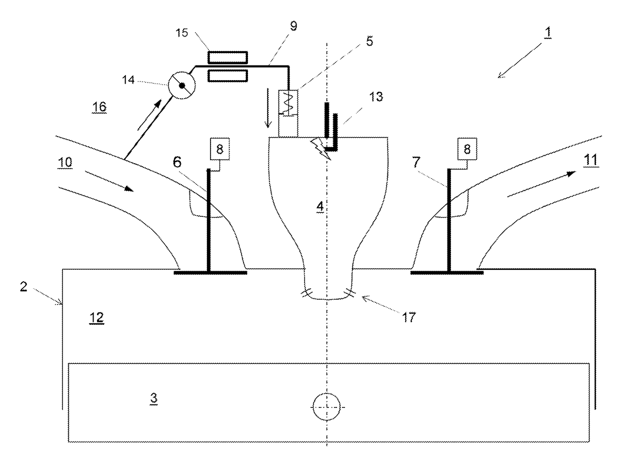
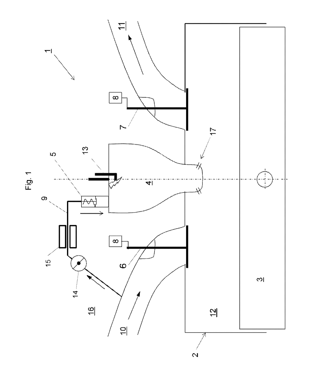
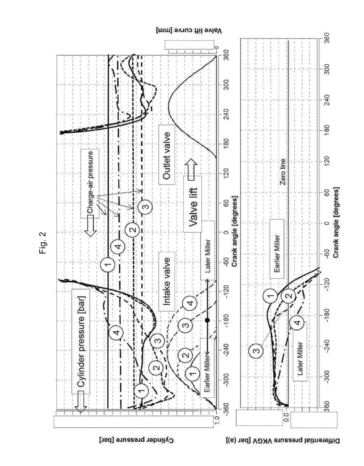
[0027]In each diagram mentioned above, the crankshaft angle.

[0028]FIG. 1 shows a cylinder 2 in which a piston 3 is arranged so as to be movable up and down, whereby a main combustion chamber 12 is formed between the piston 3 and the cylinder 2. At its top dead center, the piston 3 with the cylinder 2 forms the so-called compression volume.

[0029]An intake duct 10 can be closed by an intake valve 6 and an outlet duct 11 can be closed by an outlet valve 7 opposite the main combustion chamber 12.

[0030]A prechamber 4 communicates with the main combustion chamber 12 via overflow holes 17 and has an ignition source 13 and a prechamber gas valve 5 in the form of a non-return valve, which is connected to a source for a gas-air mixture. In this exemplary embodiment, the intake duct 11 itself serves as this source, and a connecting line 9, which is formed as a cavity in the cylinder head 15, is provided for the prechamber gas valve 5. To regulate the quantity of gas-air mixture that can be fed...


PUM


Abstract

An internal combustion engine with a cylinder head and at least one piston-cylinder unit, in which, in a cylinder, a piston can be moved between a bottom and a top dead center position, where, in the cylinder, between the piston and the cylinder head a main combustion chamber is formed, which communicates with a prechamber which has a prechamber gas valve, and where the intake and outlet valves of the main combustion chamber are actuated by an actuator, where the prechamber gas valve is connected to a source for a gas-air mixture and the prechamber charge consists of a gas-air mixture with a lambda higher than 1.2, preferably higher than 1.5 and particularly preferably higher than 1.7, and the actuator is configured such that the intake valve closes before the piston reaches the bottom dead center position, where the piston is designed as a flat piston.

Description

BACKGROUND OF THE INVENTION[0001]This invention relates to an internal combustion engine with the features of the preamble of claim 1 and a method with the features of the preamble of claim 6.[0002]It is known that internal combustion engines, in particular gas engines, can be designed as direct ignitors with a displacement volume of up to approximately 3 liters. In the case of direct ignitors, a spark plug protruding into the main combustion chamber directly ignites the gas / air mixture present in the main combustion chamber. The disadvantage of direct ignitors is that the quality of the ignition of the gas-air mixture depends entirely on the spark plug. Even minimal wear and tear of the spark plug becomes noticeable due to cycle fluctuations (fluctuations in the center of gravity of the combustion). However, to operate at maximum efficiency, it is important to operate the internal combustion engine as close as possible to the knocking limit. Despite this, if cycle fluctuations must...

Claims


Application Information

Patent Timeline
IPC IPC(8): F02B19/10F02B19/12F02M35/10F02F3/28F02D19/02
CPCF02B19/1014F02B19/12F02M35/10144F02F3/28F02B19/1009F02D19/02F02B2275/32F02B63/04F02D13/0269F02M21/02F02B2201/04F02D19/0642F02D41/0025F02D41/0027F02B19/108Y02T10/12Y02T10/30
Inventor FUCHS, JOCHEN AUGUST
Owner GE JENBACHER
Why Eureka
Eureka Blog
Learn More